. . . . .
control circuit.
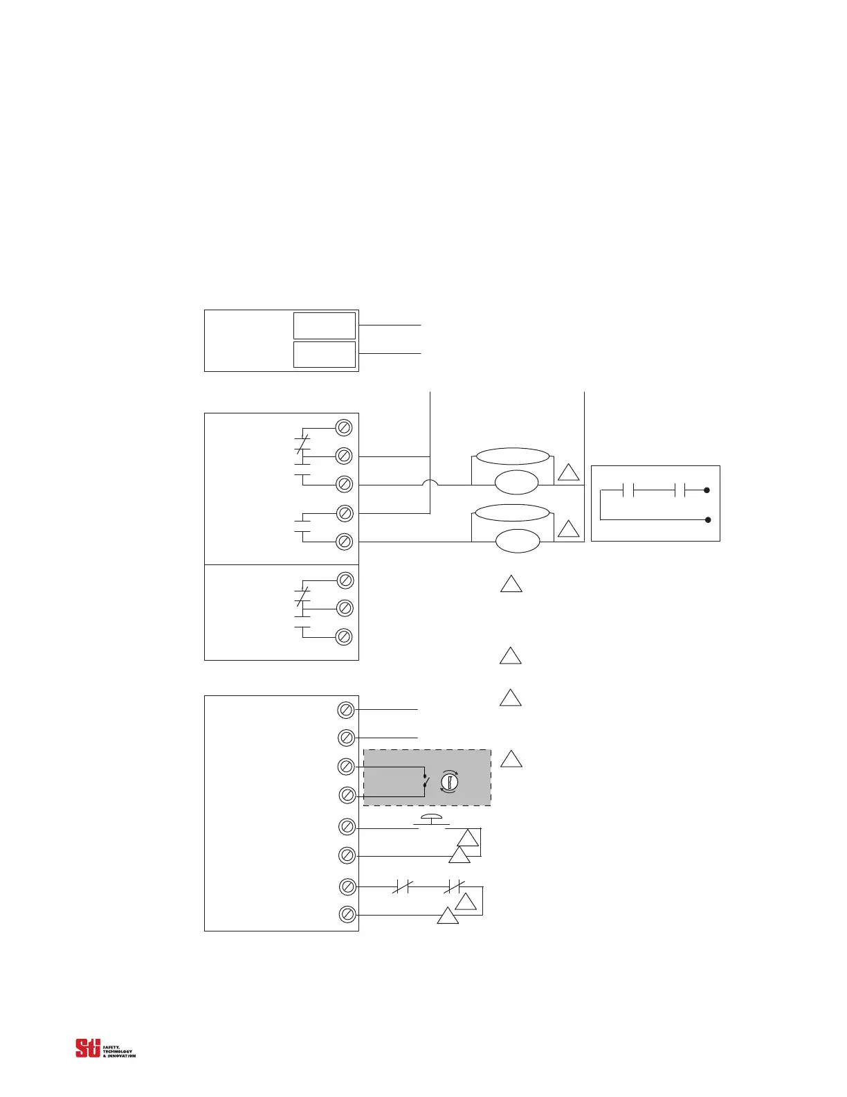
TB1
Terminals on Main Board
Line /
24 VDC
Neutral /
0 VDC
TB2
Terminals on Relay Board
OS S D 1
OS S D 2
TB3
Auxiliary
TB7
Terminals on Main Board
1
START
Preferred Connection Diagram for Two Normally Open Contacts
MPCE 1
MPCE 2
System control voltage
arc suppressor
arc suppressor
MPCE 1
MPCE 1
Notes:
Arc suppression devices should only be
installed across the coils of the machine control
relays. Never install arc suppressors across the
contacts of the safety light curtain. Failure of the
arc suppressor in a short condition, across the
contacts, will result in an unsafe condition.
No external power is to be applied to terminals
on TB7.
The relay contacts on the MPCE1and MPCE2
must be force-guided contacts. To activate
this function, Jumper 2 on the main board needs
to be installed in the ON position.
See Figure 3-5, item 22.
A N.C. or N.O. Remote Start input is selectable;
a momentary N.O contact is shown. The selection
jumper, Jumper 1 is located under the lid.
See Figure 3-5, item 19.
Verify correct voltage requirement
before appl yi ng power.
Machine control contacts
MPCE 1 MPCE 1
1
2
3
4
1
1
2
2
3
4
2
MPCE
1
2
1
2
Program
Sel 1
Sel 2
Must be accessible only by key.
MCS