3
OMRON SCIENTIFIC TECHNOLOGIES INC.
Fremont CA USA
Tel: 1/888/510-4357 in USA and Canada
© OSTI 1209 PN99584-0050 Rev. E
Original Instructions
14
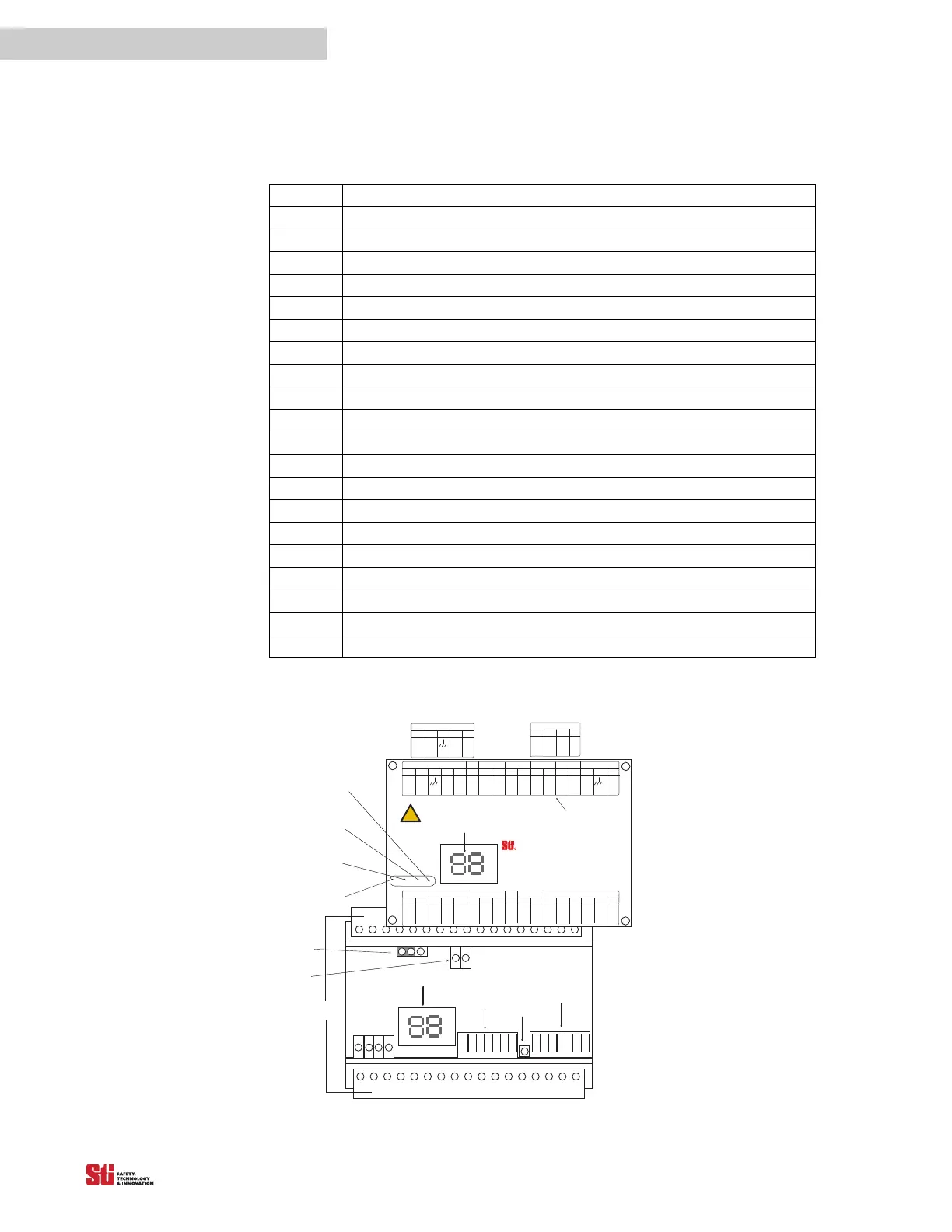
Table 3-2
Chart #
4 EXact Channel Select 1 beam
5 EXact Channel Select 2 beams
6 EXact Channel Select 3 beams
7 EXact Channel Select Return
9 Channel Selector Floating Blanking Indicator - Amber
10 Interlock or Alarm Indicator - Yellow
11 Machine Stop Indicator - Red
12 Machine Run Indicator - Green
13 Diagnostic Code Display
14 Switch A
15 Program Button
16 Switch B
17 Removable Terminal Blocks for input and output connections
18 DeviceNet status indicators (optional)
19 Start Switch Type Jumper
20 Relay Board (metal chassis only)
21 Power In (metal chassis only)
22 MPCE Monitoring (metal chassis only)
23 Multi-channel Select terminals
24 Optional Keyswitch
System Component Identification for the LCM-1, LCM-2 and LCM-3 Controllers
12
11
9
10
15
14
16
13
17
NOTE: For DeviceNet Option,
LCM-2 Series,
Terminals 13 to 17
are indicated below.
131415
DeviceNet
CAN +
DATA H
1617
DATA L
CAN VÐ
13
LCM-1 Series
Fremont, CA, USA
Tel: 510/608-3400, Fax: 510/744-1442
www.s ti.com
Scientific Technologies Inc.
OSSD 1
OSSD
RETURN
MPCE
0 VDC
MPCE
RETURN
BLUE
AUX1
OUT
ORANGE
OSSD 2
AUX2
OUT
BLACK
PINK
GRAY
VIOLET
TAN
YELLOW
RED
R
11
12
131415 123
4
57
8
6910
Xmtr
24232221201918 34333231302827 292625
Rcvr
Do not defeat or bypass. S evere injury to
!
WARNING SAFETY DEVICE
personnel could result.
START
RETURN
START
+24 VDC
WHITE
BROWN
Xmtr/R cvrOutput
SHIELD
RS232 MPCE Remote
Power
Not Used
PROG RET
PROGRAM
Not Used
Not Used
FB/CS
Interlock
Stop
Run
Not Used
Not Used
DATA
1617
Not Used
Not Used
18
1
23
19
23
45
C ha nne l S elect
ECS 1
67
PROGRAM
ECS Return
ECS 2
NOTE : For Multi Channel S elect Option,
LCM-3 Series,
Terminals 4 to 7
are indicated on below.
CS Prog
Figure 3-4 DIN Controller Components