. . . . .
OMRON SCIENTIFIC TECHNOLOGIES INC.
Fremont CA USA
Tel: 1/888/510-4357 in USA and Canada
© OSTI 1209 PN99584-0050 Rev. E
Original Instructions
13
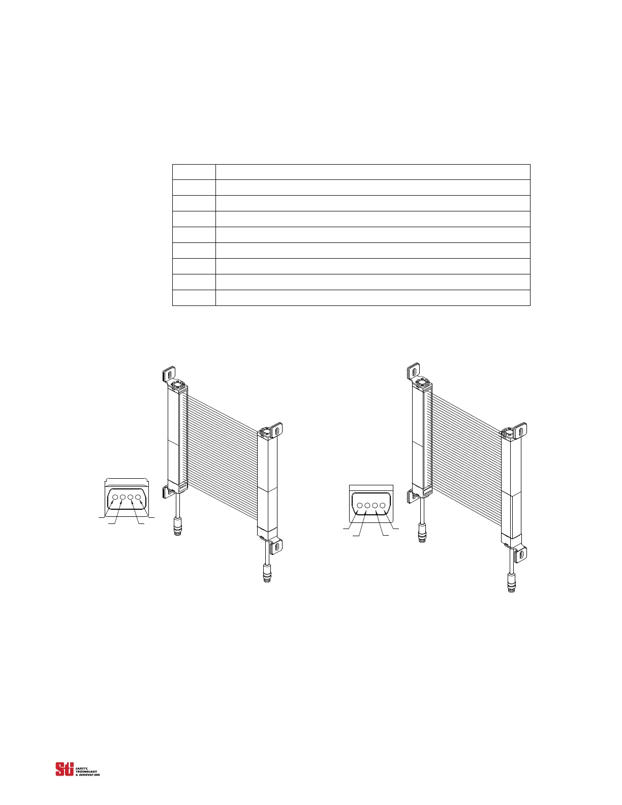
3.2 LOCATION OF THE COMPONENTS AND INDICATORS
Refer to Figure 3-3, Figure 3-4 and Figure 3-5 for the location of the components and indicators listed
below.
Table 3-1 System Component Identification
Chart #
1 RECEIVER
2 Individual Beam Indicators (one for each beam) – Red
3 Channel Select or Floating Blanking Indicator – Amber
4 Interlock or Fault Indicator – Yellow
5 Machine Stop Indicator – Red
6 Machine Run Indicator – Green
7 TRANSMITTER
8 Detection Zone
for the 4700 Transmitter and Receiver
2. YEL
4. RED - STOP/BLOCKED
3. GRN - RUN/CLEAR
2. YEL - INTERLOCK
OR CHANNEL SELECT
1. AMBER - FLOATING BLANKING
1. AMBER
4. RED
3. GRN
INDICATORS
LED
RECEIVER
DETECTION
ZONE
TRANSMITTER
MC4700
MC4700
2. YEL
4. RED - STOP/BLOCKED
3. GRN - RUN/CLEAR
2. YEL - INTERLOCK
OR CHANNEL SELECT
1. AMBER - FLOATING BLANKING
1. AMBER
4. RED
3. GRN
INDICATORS
LED
RECEIVER
DETECTION
ZONE
TRANSMITTER
MS4700
MS4700
Figure 3-3 4700 Transmitter and Receiver