. . . . .
OMRON SCIENTIFIC TECHNOLOGIES INC.
Fremont CA USA
Tel: 1/888/510-4357 in USA and Canada
© OSTI 1209 PN99584-0050 Rev. E
Original Instructions
67
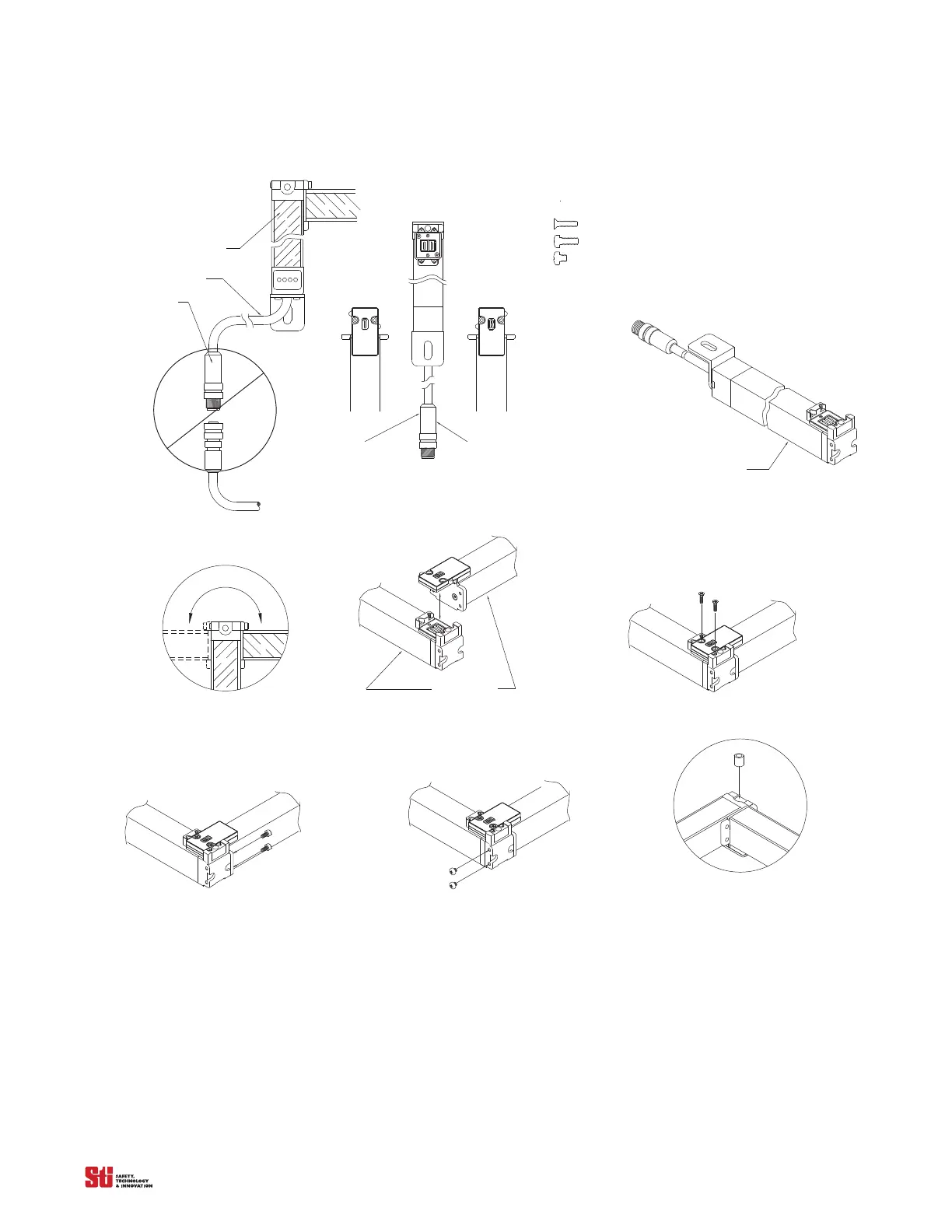
Figure 14-5
Red = Receiver
Blk = Transmitter
Receiver
Trans mitter
Step 2
Identify & separate the transmi tter and receiver segments.
For cabled segments, Red connectors are receiver,
Black connectors are transmitter.
Blk = Transmitter
Red = Receiver
Connector
Cable
Filter
Step 1
Unit m
ust be assembled
without power suppli ed.
face down
Filter
Step 3
Place segment (with cable) lens down on a flat surface.
Optional spacer (STI 83137)
Flat head phillips; M2.5x11 (STI 90835)
Round head phillips; M3x8 (STI 91141)
Round head phillips; M3x3 (STI 90815)
Note:
2-
2-
2-
The following screws are used for each 90 joint:
Step 4
Each segment may be joined to the left or right.
Filter face down
Step 5 Ass emble segments together as shown.
Step 6
Install two flathead phillips screws (90835) as shown.
Step 7
Install two round head phillips screws (91141) as shown.
Step 8.
Install two round head phillips screws (90815) as shown.
Step 9
Use optional mounting spacer (83137) as shown.
Assembly Instructions Steps
14.4.4 INSTALLATION
After the unit is assembled in the desired configuration, measure the mounting holes on the configured
system. Confirm these dimensions by using the drawing Figure 14-2 & Figure 14-4. The mounting
holes should match within a reasonable tolerance. Use the dimensions from the drawing for proper
alignment.
The first segment is the segment which connects to the power supply/controller. Make sure the first
transmitter
is mounted dire
ctly across from the first receiver segment. This orientation must continue