. . . . .
OMRON SCIENTIFIC TECHNOLOGIES INC.
Fremont CA USA
Tel: 1/888/510-4357 in USA and Canada
© OSTI 1209 PN99584-0050 Rev. E
Original Instructions
23
Table 5-8
Total Number of Beams
Disabled by Exact Channel
Select and/or Floating Blanking
Minimum
Object Resolution S
Depth Penetration Factor, Dpf
for use with ANSI Formula
(Dpf
= 3.4 (S-.276) inches)
None 30 mm (1.18 inches) 3.07 inches (78.0 mm)
1 Beam 52 mm (2.05 inches) 6.03 inches (153.2 mm)
2 Beams 74 mm (2.01 inches) 8.96 inches (227.6 mm)
3 Beams 96 mm (3.78 inches) 11.91 inches (302.5 mm)
4 Beams 118 mm (4.65 inches) 14.87 inches (377.7 mm)
5 Beams 140 mm (5.51 inches)‘ 17.80 inches (452.0 mm)
etc...
Sample S and D
pf
Factors for 30 mm resolution Systems
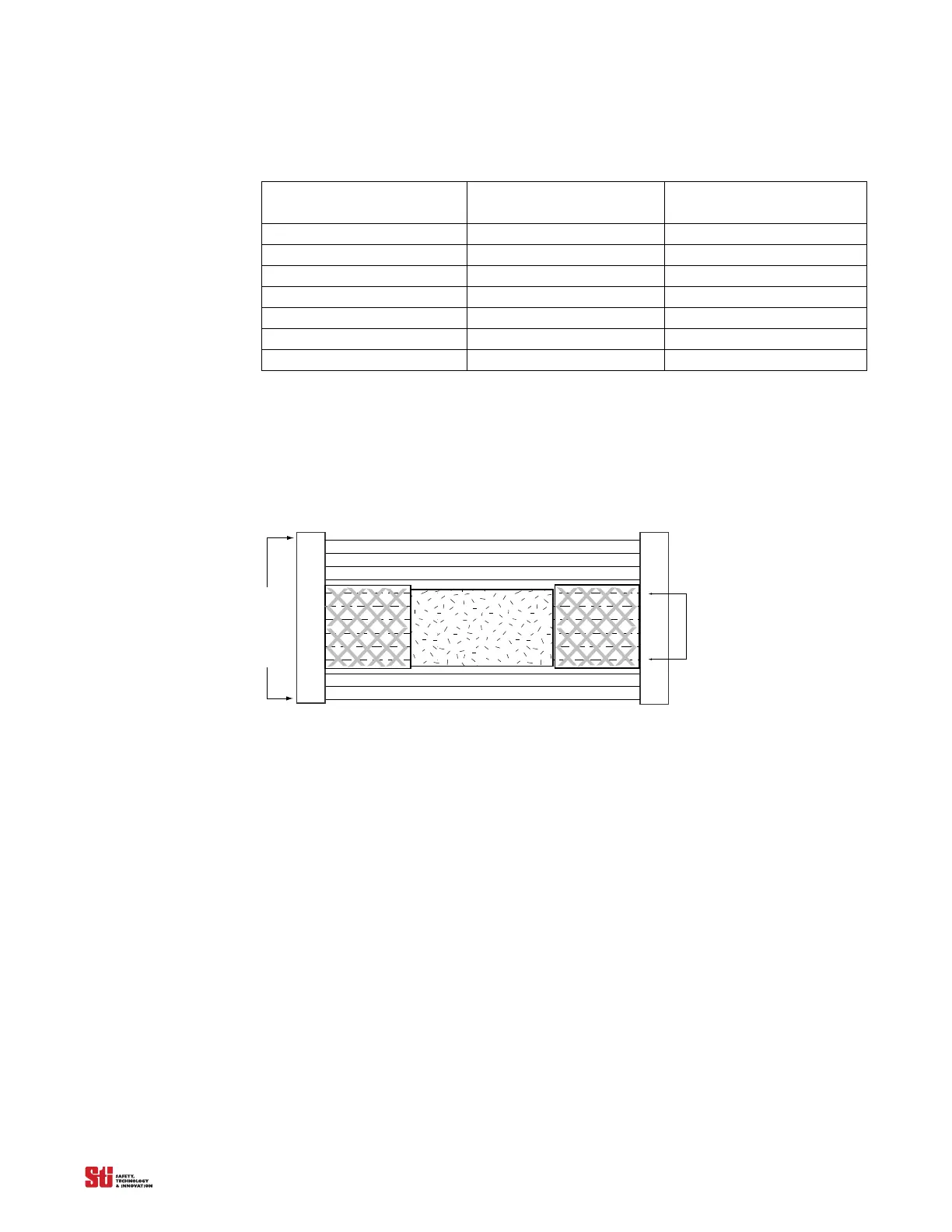
Hard guarding refers to mechanical barriers such as sheet or expanded metal, etc. See Figure 5-3
Adding Hard guarding to Light Curtain when Using Channel Select for an example.
Floating Blanking changes the resolution (object size) of the 4700 system and will require different
mounting distance
.
Light
Detection Zone
Light
Channel Select Area
Obstruction
Figure 5-3 Adding Hard guarding to Light Curtain when Using Channel Select
5.5 ACTIVATING AND PROGRAMMING EXACT CHANNEL SELECT
Warning! To prevent unauthorized modification of the sense field, the system controller should be installed in
an enclosure with supervisor-controlled access.
Exact Channel Select is activated by setting position 4 of Switches A and B, located under the
controller cover. Refer to Figure 3-1. Any mismatch between the settings of the switches will result in
a alarm condition.
To program an ECS pattern, the 4700 system must be in the machine stop state. An ECS pattern is
stored
by blocking th
e appropriate area of the detection zone and pressing, then releasing the program
button (See Figure 3-4 and Figure 3-5 for locations). The MCS works the same as the ECS except in
addition to blocking the appropriate area of the detection
zone, an four position binary
switch or PLC
or two SPST switches are needed to differentiate the four possible pattern.
5.6 MCS PROGRAMING
1. Ensure that power is supplied to the controller, and that the light curtain is green and showing all
beams are clear. The display should read “00”.
2. Set position 4 of switches A and B to the closed position a
nd press “Start”,
the display should red
“03”.