14
OMRON SCIENTIFIC TECHNOLOGIES INC.
Fremont CA USA
Tel: 1/888/510-4357 in USA and Canada
© OSTI 1209 PN99584-0050 Rev. E
Original Instructions
66
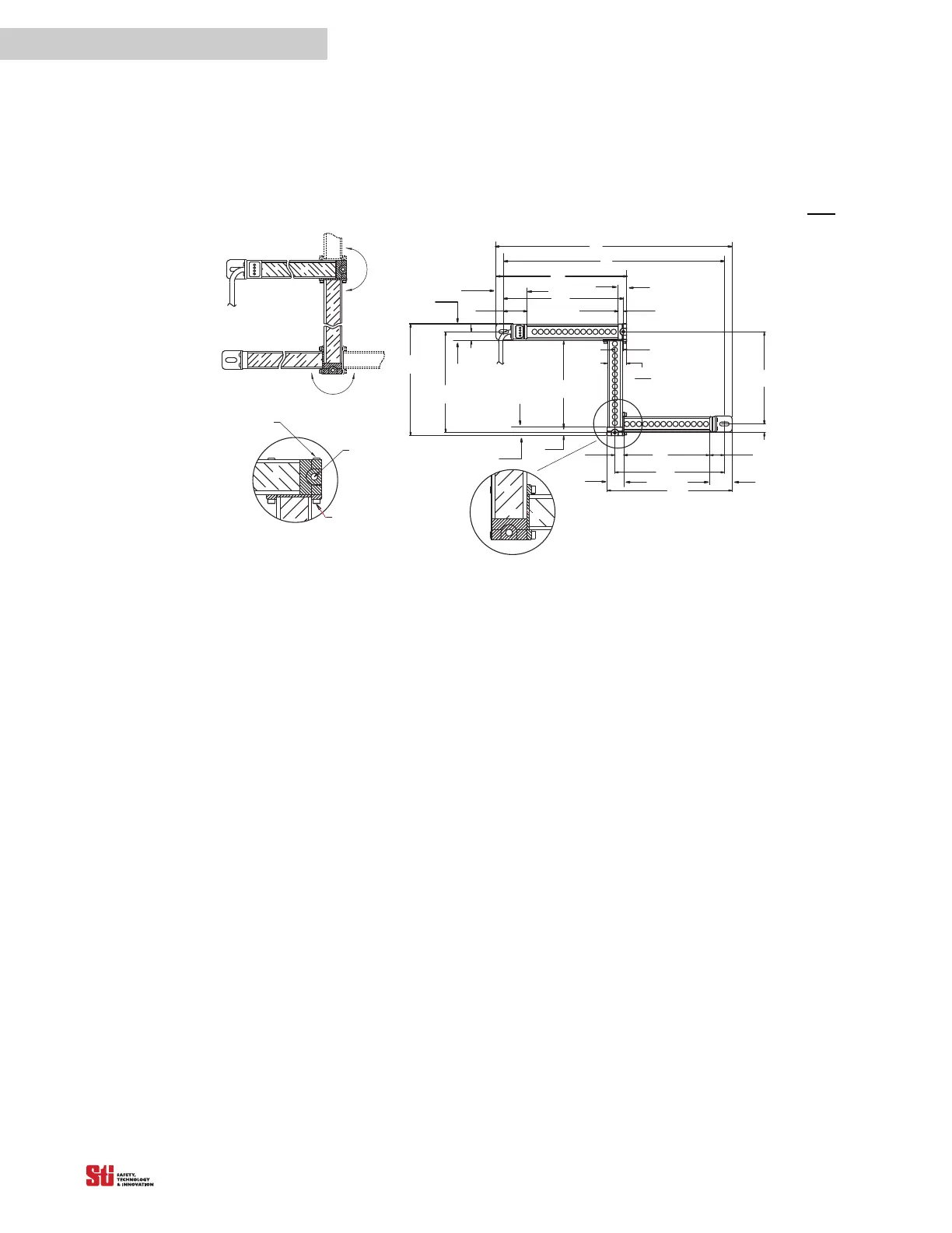
14.4.2 90° JOINTED MICROSAFE MCJ4700 DIMENSIONS
ASSEMBLY CONFIGURATIONS & MTG DIM'S
E
D
A2
A1
A
B
B1
C
C1
C2
B2
41. 4
1. 63
15. 8
0. 62
9. 3
0. 37
15. 9
0. 58
33. 5
1. 32
9. 3
0. 37
15. 8
0. 62
25. 9
1. 02
F
55. 0
2. 17
28. 8
1. 125
14. 8
0. 58
29. 8
1. 125
39. 5
1. 55
14. 8
0. 58
Mid
First
Last
CABLE
REMOVABLE
PLUG (X4)
USE M5
SCREW
M3 SHCS (X4)
Mounting dimension formulas based on detection zones A, B, C
A = Detection Zone (First Segment)
A1 = A + 50.7 mm (1.99 in.) (mounting holes)
A2 = A + 69.8 mm (2.75 in.)
B = Detection Zone (Middle Segment)
B1 = B + 25.1 mm (0.99 in.) (mounting holes)
B2 = B + 44.6 mm (1.76 in.)
C = Detection Zone (Last Segment)
C1 = C + 41.7 mm (1.64 in.) (mounting holes)
C2 = C + 68.9 mm (2.72 in.)
D = A1 + C1 – 15.0 mm (0.59 in.) (mounting holes)
E = A2 + C2 – 33.5 mm (1.32 in.)
F = B1 – 15.0 mm (0.59 in.) (mounting holes)
Dimensions in
mm
in.
Figure 14-4 90° Jointed MicroSafe MCJ4700 Dimensions
14.4.3 SENSOR ASSEMBLY INSTRUCTIONS
It is possible to assemble the joints in either a 90 or 270-degree orientation. Prior to assembling the
sensor, verify the desired configuration of the segments. Power must not be connected during
assembly. Ensure that receiver segments are mounted to receiver segments, and transmitters are
mounted to transmitter segments. The receiver first segment has a red connector on the cable, and the
other receiver segments are identified with a “R” on the joint. Transmitters are identified with a “T”.