. . . . .
OMRON SCIENTIFIC TECHNOLOGIES INC.
Fremont CA USA
Tel: 1/888/510-4357 in USA and Canada
© OSTI 1209 PN99584-0050 Rev. E
Original Instructions
17
from machine run to machine stop and remain in this state until the obstruction is removed. Once the
detection zone is clear, the 4700 system will automatically change from machine stop to machine run.
4.2.2 START INTERLOCK
The 4700 system will power-up with its safety outputs OFF and perform system initialization and self-
tests. If no obstructions are detected in the protected zone, (or an exact channel select pattern satisfied),
the 4700 system enters the interlock state. To enter the machine run state, the detection zone must be
clear (or an exact channel select pattern satisfied), and then the operator must press and release the start
switch. In the machine run state, when an object is sensed entering the detection zone the 4700 system
will change from machine run to machine stop. Once the detection zone is clear, the 4700 system will
automatically change from machine stop to machine run.
4.2.3 START/RESTART INTERLOCK
The 4700 system will power-up with its safety outputs OFF, and, if no faults are detected, enter the
interlock state. To enter the machine run state, the detection zone must be clear (or an exact channel
select pattern satisfied), and then the operator must press and release the start switch. In the machine
run state, when an object is sensed entering the detection zone the 4700 will change from machine run
to interlock. The 4700 system will remain in the interlock state even after the obstruction is removed
from the detection zone. To enter the machine run state, the operator must press and release the start
switch. If any obstruction is present in the detection zone when the start switch is pressed and released,
the 4700 will remain in the interlock state.
NOTE! The definitions above mention a start switch. See Section 10–“Connecting to the Machine
Control Circuit” for wiring of the start switch.
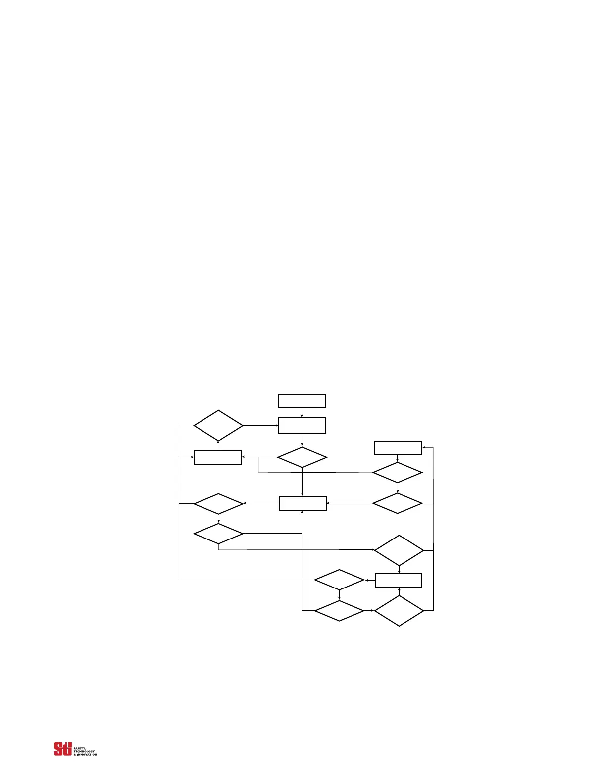
Power-Up
Power-On
Self-Test
Failure
Machine S top
Start
Pressed &
Released
Fault
Failure
Beam
Cleared
Machine run
Failure
Beam
blocked
Start/
Restart
Interlock
Interlock
Failure
Beam
Blocked
Start
Pressed &
Released
No
Yes
No
No
No
No
No
No
YesYes
YesYes
Yes
Yes
Yes
Yes
Yes
Yes
Figure 4-1 Functional Flow Diagram