. . . . .
OMRON SCIENTIFIC TECHNOLOGIES INC.
Fremont CA USA
Tel: 1/888/510-4357 in USA and Canada
© OSTI 1209 PN99584-0050 Rev. E
Original Instructions
39
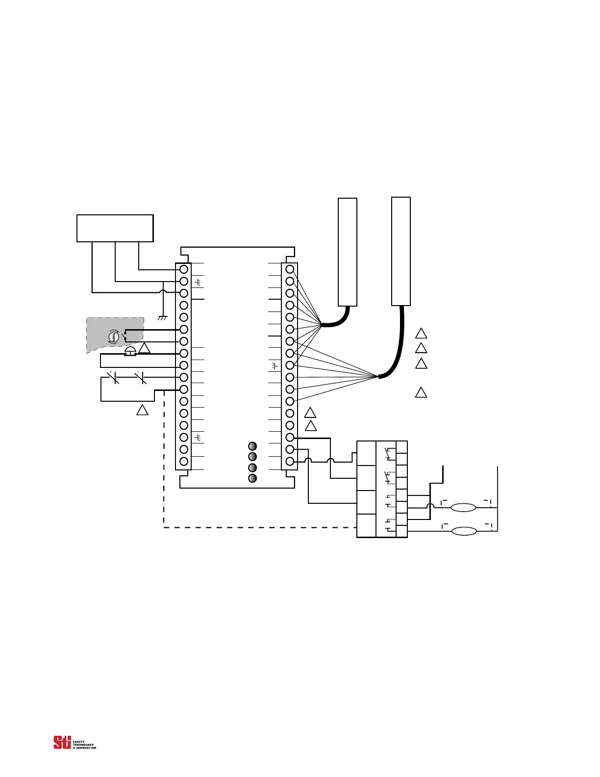
10.1.2 CONNECTING VIA AN RM-1 MODULE
The STI RM-1 Module provides force-guided relay outputs for machine control. (OSSD) Safety
outputs 1 and 2 are connected to the RM-1 and provide the power necessary to energize its relays. See
Figure 10-2 for the preferred connection method using the RM-1. The auxiliary non-safety output of
the 4700 system can be used to signal light curtain status to a PLC.
OS S D
RTN
MPCE
AUX 1
OUT
GRAY
WHITE
DATA L
CAN V-
START
RETURN
Control Voltage
PINK
BLACK
+2 4V DC
BLUE
RM1 MODULE
OR ANGE
BROWN
OS S D1
0 VDC
START
MPCE
RETURN
DATA H
CAN V+
OSSD 2
AUX 2
OUT
YELLOW
RED
FB/CS
Interlock
Stop
Run
Receiver
Transmitter
MPCE 2
MPCE 1
+24 VDC GROUND 0 VDC
POWER SUPPLY
2. 25A 24 VDC 54VA
TAN
VIOLET
34
33
32
31
30
29
28
27
26
25
24
23
22
21
20
19
18
Must be accessible only
by key.
Arc S uppres s or
42
41
32
31
24
23
14
13
OS S D 1
OS S D 2
0 VDC
Monitor
MPCE 1
Arc Suppressor
MPCE 2
Auxi l i ary Output 1: NPN, 100 mA max. ,
30 VDC max.
Auxi l i ary Output 2: PNP, 500 mA max. ,
Vs upply -2V
MPCE sensing must be used with the RM1.
The user can choose to monitor the MPCE
contacts of the guarded machine directly or
the safety relay outputs of the R M1.
1
2
3
4
If remote S TAR T is not used, connect STAR T
output to STAR T R ETUR N.
4
3
1
2
1
2
3
4
5
6
7
8
9
10
11
12
13
14
15
16
17
Figure 10-2 Connecting via an RM-1 Module