10
OMRON SCIENTIFIC TECHNOLOGIES INC.
Fremont CA USA
Tel: 1/888/510-4357 in USA and Canada
© OSTI 1209 PN99584-0050 Rev. E
Original Instructions
38
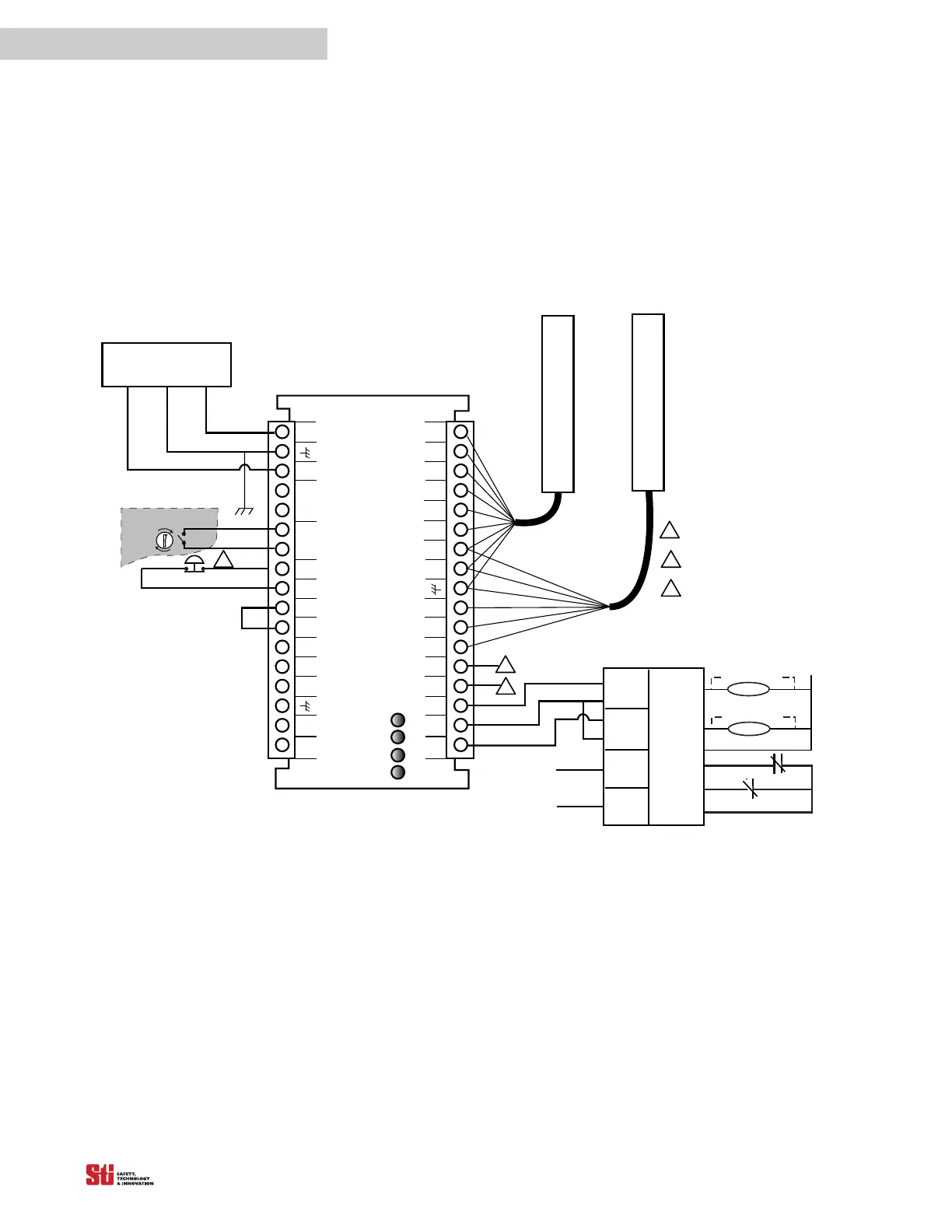
10.1.1 CONNECTING TO A SAFETY MONITORING DEVICE
The wiring from the 4700 system to the machine control circuit must be control reliable as described in
ANSI B11.19-1990. Normally PLCs are not designed to be control reliable. Safety devices, such as the
4700 system should not depend on a PLC to stop a guarded machine.
However, safety related monitoring devices are now available. See Figure 10-1 for connection to such
a device. Note that all safety inputs are directed to the monitoring device which also performs the
MPCE monitoring
function.
OS S D
RTN
TAN
MPCE
AUX 1
OUT
GRAY
VIOLET
WHITE
DATA L
CAN V-
START
RETURN
PINK
BLACK
+2 4V DC
BLUE
LCM Controller
OR ANGE
BROWN
OS S D1
0 VDC
START
MPCE
RETURN
DATA H
CAN V+
OSSD 2
AUX 2
OUT
YELLOW
RED
FB/CS
Interlock
Stop
Run
Receiver
Transmitter
MPCE 2
+24 VDC EARTH 0 VDC
POWER SUPPLY
LCM
INPUT 1
LCM
INPUT 2
SAFETY
INTERLOCK
INPUTS
OT HER
SAFETY
DEVI CES
Safety Moni toring Device
MPCE
Moni tori ng
Output 1
Output 2
MPCE 1
2. 25A 24 VDC 54VA
1
2
3
4
5
6
7
8
9
10
11
12
13
14
15
16
17
34
33
32
31
30
29
28
27
26
25
24
23
22
21
20
19
18
PROGRAM
Arc Suppressor
MPCE 2
MPCE 1
Arc Suppres s or
Auxi l i ary Output 1: NPN, 100 mA max. ,
30 VDC max.
Auxiliary Output 2: PNP, 500 mA max. ,
Vsupply -2V
1
2
3
If remote S TAR T i s not used, connect STAR T
output to START RETURN.
1
2
3
Must be accessible only
by key.
Figure 10-1 Connecting to a Safety Monitoring Device