1 2 3451 2 3 456 7 8
2
1
2
1
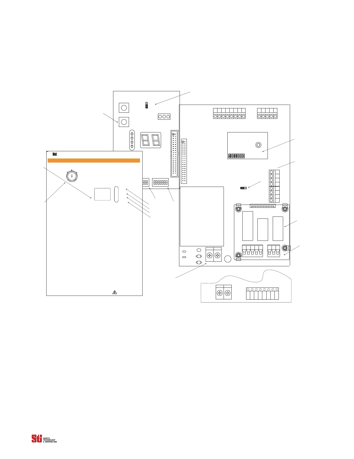
MPCE MON
ON
OFF
JMP2
BOARD
DEVICENET
OPTIONAL
-Note: Shown with optional Relay Board.
P2
R44
R45
C8
C9
RV1
MCS
TB5
TX
TB6
RX
J1
J3
TB7
AUX
K2
K1
0SSD2 AUX
TB3
TB1
TB2
PS1
0SSD1
F1
N
L
KEYSWITCH
J2
N. O.
N. C.
PROGRAM
START
J1
SWA
SWB
STO P
R UN
RUN
STA R T
INTERLOCK
FB/ CS
W A R N I N G
Scientific Technologies Inc, Fremont, CA 94555 U. S. A.
R
!
T
o test the light curtain, use the appropriate ST I-
supplied test object, or properly sized opaque cylindrical
object.
If you are using the Channel Select or Floating
B lanking features and the object to be ignored does not
completely prevent access to the hazardous area, either
(1) use a mechanical guard or other means to block
access or (2) increase the minimum safe distance and
use a larger test object diameter as explained in the
In
stallation and Operating Manual.
1. Disable the machine. Power on the light curtain.
2. Inspect the machine to ensure entry to the
hazardous area is only through the light curtain sensing
field. If not, additional guarding, including mechanical
barriers may be required.
3. Verify that the mounting distance of the light
curtain is equal to or greater than the minimum safe
distance from the hazardous point. E nsure the operator
is not able to stand un
detected between the light curtain
and the hazard.
4. Check for external damage to the light curtain,
the machine, electrical cables and wiring.
5. Interrupt the sensing field with the
test
object t
o check the effectiveness of the light curtain.
Move the test object inside the perimeter (along the top,
Do Not Remove Or Cover This Label
http://www.sti.com1/ 888/ 510-4357
S TI L abel P/N 28621-0010 re
T
ES T
P
R O CEDUR E
sides and bottom) of the sensing field and up and down
through the center of the sensing field. Verify that the
R ed indicator is ON and the Green indicator is OF F while
the test object is anywhere in the sensing field.
watch for any unprotected access to the point of hazard.
6. Start the machine. Interrupt the sensing field
wi th the test object. T he machine should stop
immediately. Never insert the tes
t object i nto the
dangerous parts of the machine! With the machine at
rest, interrupt the sensing field with the test object.
that the machine will not start with the test object in the
sensing field.
7. E nsure the braking and machine stop systems
are working properly in accordance with the machine
manufacturerÕs requirements. If the machine does not
stop fast enough, adjust the braking system or increase
the distance from the light curtain to the
point hazard.
8. If the safety devices or machine fail any of these
tests, do not run the machine. Immediately lockout the
machine to prevent its use and notify the supervisor
9. If the Channel Select is reprogrammed or
disabled, you must repeat these test procedures.
10. Close and lock the light curtai n contr
enclosure door, if applicable.
Dia g no stic C od es :
00 Normal O peration
01 Normal O peration, waiting for Start signal
02 Normal O pera
tion, Floating Blanking a ctive
03 Normal O peration, Exact Channel Select a ctive
04 Normal O peration, Exact Channel Select a nd
Floating Blanking a ctive
20 G eneral DIP switch fault
21 Invalid switch setting
22 DIP switch settings changed during operation
23 Invalid C hannel Select or MPCE switch settings
30 G eneral Safety O utput fault
40 G eneral MPCE fault
41 MPCE open before safety output (O SSD) activation
43 MPCE open when power is applied
5
0 Internal controller fault
51 Receiver fault
52 Transmitter fault
53 Transmitter and receiver length mismatch or transmitter
and receiver not connected
59 24 V DC power supply fault
Inside Front Lid of the metal chassis controller
19
15
16
14
18
17
20
21
13
9
10
11
12
23
TB4
TB1
Shown with DC Solid State Configuration
Note: For Solid State Configuration, JMP2 and
PS1 are not available.
+
_
22
PR O G RA M
24
2
1
2
1
PROG
START
MPCE
. . . . .