. . . . .
OMRON SCIENTIFIC TECHNOLOGIES INC.
Fremont CA USA
Tel: 1/888/510-4357 in USA and Canada
© OSTI 1209 PN99584-0050 Rev. E
Original Instructions
19
5.1 EXACT CHANNEL SELECT (ECS)
ECS disables selected, fixed areas of the detection zone by masking off specific, fixed beam locations.
ECS is helpful when stationary objects such as tooling and fixtures permanently obstruct a portion of
the detection zone.
ECS requires that any portion of the detection zone which is block
ed remain blocked
. If the obstruction
is removed the 4700 system will enter a machine stop state. When selecting channels to be masked, one
channel must remain unblocked. A channel is defined as one transmitter/receiver pair or “beam”.
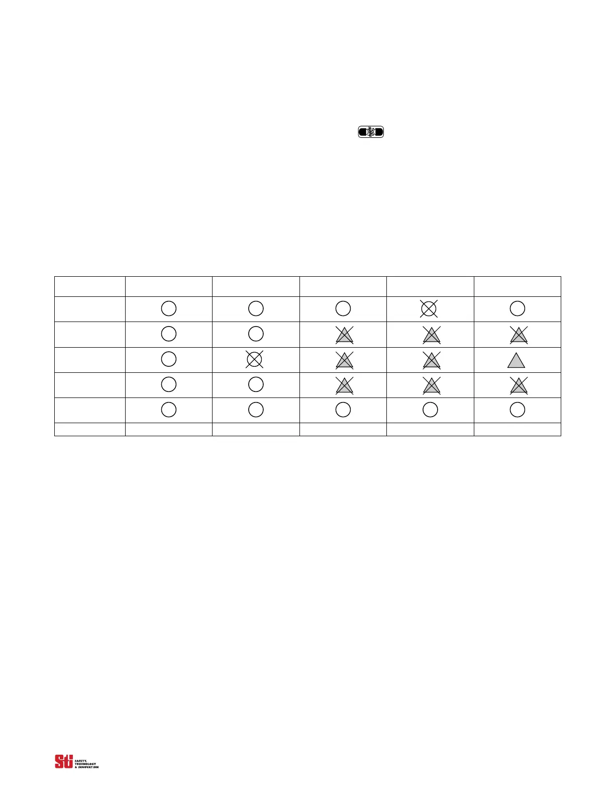
See Table 5-1, System Response to Exact Channel Select for a diagram of 4700 system response during
operation with ECS active.
Table 5-1
Channel Select
Statu
s
Exact Channel Select
Inactive
Exact Channel Select
Inactive
Exact Channel Select
Active
Exact Channel Select
Active
Exact Channel Select
Active
Channel 1
Channel 2
Channel 3
Channel 4
Channel 5...
System Response
machine run machine stop machine run machine stop machine stop
System Response to Exact Channel Select
5.2 MULTI CHANNEL SELECT (MCS)
MCS stores up to four patterns of selected beams. Just as the ECS disables selected, fixed areas of the
detection zone by masking off specific, fixed beam locations, the MCS can be programmed to store
four different patterns. MCS is helpful when a machine requires multiple setups where stationary
objects such as tooling, fixtures, or material frequently obstruct a portion of the detection zone. Access
and programming is performed using a PLC or switch inputs. The suggested logic patterns for
identification of the stored program are in Table 5-2 on page 20. Refer to drawings Figure 5-1 and
Figure 5-2 for connection recommendations.