. . . . .
OMRON SCIENTIFIC TECHNOLOGIES INC.
Fremont CA USA
Tel: 1/888/510-4357 in USA and Canada
© OSTI 1209 PN99584-0050 Rev. E
Original Instructions
31
9 I
NSTALLATION
9
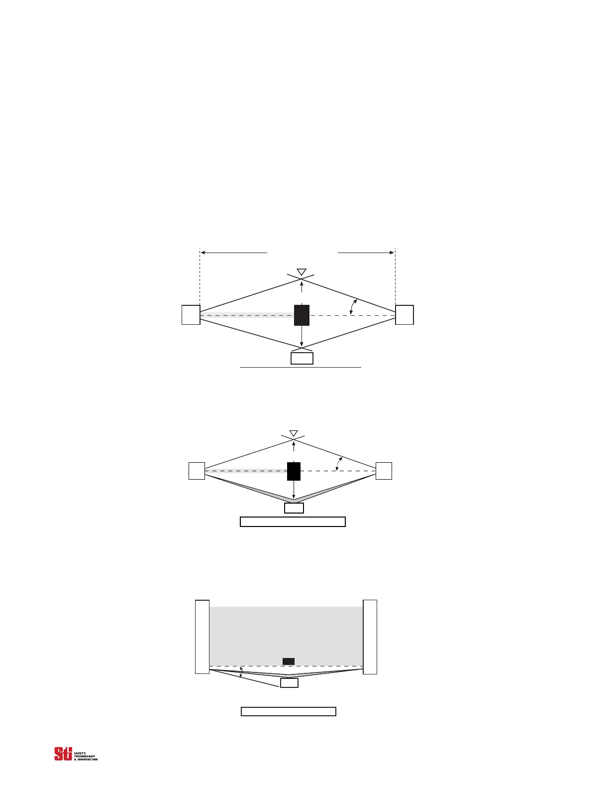
9.1 REFLECTIVE SURFACE INTERFERENCE
A reflective surface adjacent to the detection zone can deflect the optical beam and may cause an
obstruction in the zone not to be detected. (See Figure 9-2 and Figure 9-3.) The reflective surface may
be part of the machine, mechanical guard or workpiec
e. Therefore,
a minimum distance (d) must exist
between the reflective object and the center line of the 4700 system detection zone. The Test Procedure
(Appendix B)
must be used to test for this condition.
Trans mitter
Receiver
Approach direction
Central beam
L ight beam interrupted
d
Reflective Surface
Interruption
a
Beam Angle, a
Operating Range, R
Figure 9-1 Correct Mounting Example with Proper Alignment
The interruption is clearly detected. The reflective object is outside of the beam angle
Trans mitter
Receiver
Approach direction
Central beam
L ight beam interrupted
d
Reflective Surface
Perimeter of danger area
Reflection
Interruption
a
Beam Angle, a
Figure 9-2 Unsafe Mounting Example
The interruption is not detected because of the reflection. The reflective object is inside the beam angle.
Receiver
Reflective Surface
Perimter of danger area
Reflection
Interruption
a
Sensing Field
Trans mitter
Figure 9-3 Unsafe Mounting Example