Chapter 3
3-28
System Design and Installation
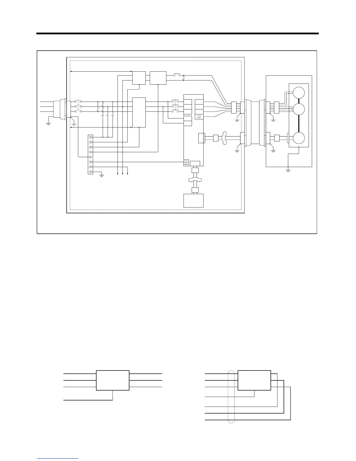
● Three-phase Power Supply Input (R7D-AP08H)
• Ground the motor’s frame to the machine ground when the motor is on a movable shaft.
• Use a grounding plate for the frame ground for each Unit, as shown in the above diagrams, and
ground to a single point.
• Use ground lines with a minimum thickness of 3.5 mm
2
, and arrange the wiring so that the ground
lines are as short as possible.
• If no-fuse breakers are installed at the top and the power supply line is wired from the lower duct,
use metal tubes for wiring and make sure that there is adequate distance between the input lines
and the internal wiring. If input and output lines are wired together, noise resistance will decrease.
• No-fuse breakers, surge absorbers, and noise filters (NF) should be positioned near the input termi-
nal block (ground plate), and I/O lines should be isolated and wired using the shortest distance pos-
sible.
• Wire the noise filter as shown at the left in the following illustration. The noise filter should be
installed at the entrance to the control box whenever possible.
NFB
L1
L2
U
V
W
CN2
CN1
R7D-A@
E
M
B
R7M-A@
L3
L1C
L2C
2 m max.
2 m max.
Control panel
Metal plate
AC
power
supply
Metal
duct or
conduit
Surge
absorber
Class D
ground
(Class 3
ground:
100
Ω or
less)
Noise
filter
Brake
power
supply
Noise
filter
Contactor
Ground
plate
Controller
power supply
Ferrite
core
Ferrite
core
Clamp
Ferrite core
Clamp
Ferrite core
Controller
Metal
duct or
conduit
Installation incorporating
Servo Motor
Ferrite
core
Ferrite
core
Note 1. The cable wiring for the ferrite core must be 1.5 turns.
Note 2. Remove the sheath from the cable and ground it directly to the metal plate at the clamps.
NF
1
2
3
4
5
6
E
NF
1
2
3
4
5
6
E
Correct: Separate input and output Wrong: Noise not filtered effectively
AC input
Ground
AC input
Ground
AC output
AC output

 Loading...


