Chapter 2
2-65
Standard Models and Specifications
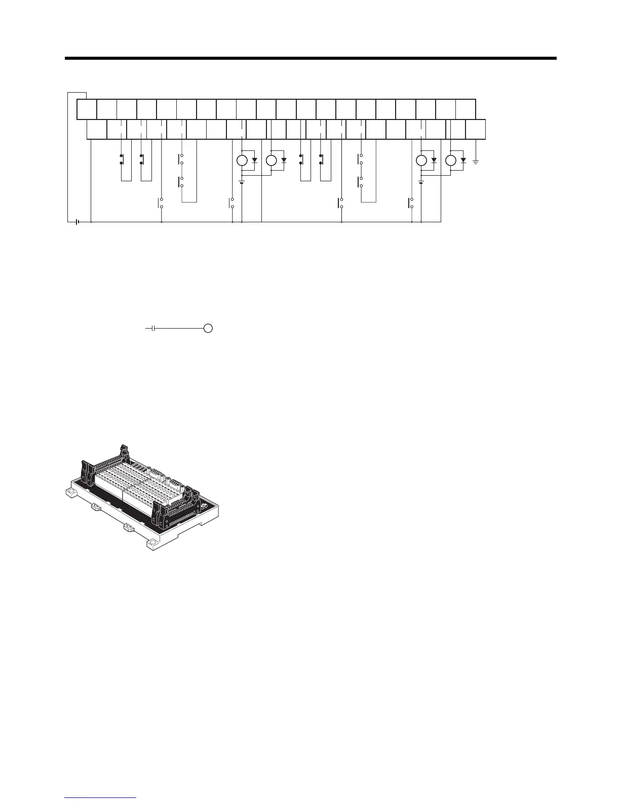
● Wiring
■ XW2B-80J7-1A
X-axis
origin
proximity
+24 V
20
0
24 V DC
24
V DC
Com-
mon
Com-
mon
Com-
mon
0 V
FG
Com-
mon
Com-
mon
IN9
X1
(See note 2.)
39
19
IN6
IN8
IN7
X-axis
CW limit
(See note 1.)
(CIO 2960.06)
X-axis
CCW limit
(See note 1.)
(CIO 2960.07)
Example:
2960.06
A540.08
Com-
mon
XB
X1
YB
Y1
24
V DC
(See note 2.)
Y1
Com-
mon
Com-
mon
Com-
mon
Com-
mon
Com-
mon
X-axis
RUN
X-axis
ALM
X-axis
BKIR
Y-axis
origin
proximity
Y-axis
RUN
Y-axis
ALM
Y-axis
BKIR
X-axis
RESET
X-axis
ALMCOM
Y-axis
RESET
Y-axis
ALMCOM
Y-axis
CW limit
(See note 1.)
(CIO 2960.08)
Y-axis
CCW limit
(See note 1.)
(CIO 2960.09)
Note1. The CW limit input signal and CCW limit input signal can be input through an Input Unit. The follow-
ing flags function as the CW/CCW limit input signals in the CJ1M:
Pulse Output 0: CW: A540.08, CCW: A540.09
Pulse Output 1: CW: A541.08, CCW: A541.09
Program the actual inputs from the Input Unit to control these flags as ladder program outputs as
shown below.
Note2. The XB contacts are used to turn ON/OFF the electromagnetic brake.
a) Do not connect anything to unused terminals.
b) The 0 V terminal is internally connected to the common terminals.
c) The following crimp terminal is applicable: R1.25-3 (round with open end).
INC
servo1
ABS _CW-
0
19
This Servo Relay Unit connects to the following OMRON
Programmable Controllers.
• CS1W-HCP22-V1
• FQM1-MMP21

 Loading...


