Let-
ter
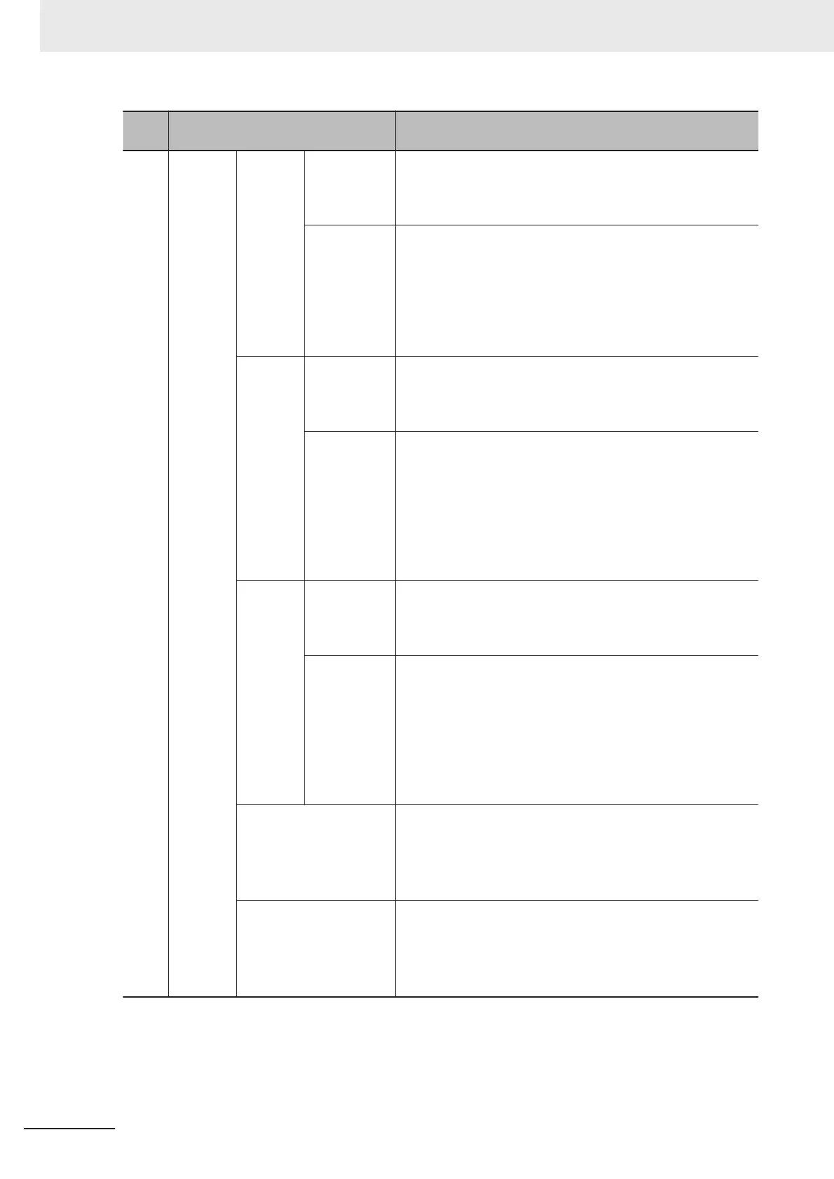
Name/Label Description
(d) Digital fil-
ter set-
tings
Digital
low-pass
filter
Setting value
of cutoff fre-
quency [×10
Hz]
Values that you set for
Ch£ Digital Low-pass Filter Cutoff
Frequency in the Unit operation settings are displayed.
For disabled channels, or channels whose sampling period is
less than 5 µs, - is displayed in the Ch column.
Actual cutoff
frequency
[Hz]
The actual cutoff frequency for each channel, which is auto-
matically calculated by the Support Software, is displayed.
*3
The digital low-pass filter of the High-speed Analog Input Unit
operates at the cutoff frequency shown here.
For disabled channels, channels whose sampling period is
less than 5 µs, or channels whose cutoff frequency is 0
, - is
displayed in the Ch column.
Moving
average
filter 1
Setting num-
ber of moving
average
[times]
Values that you set for Ch£ Filter 1 Moving Average Count
in the Unit operation settings are displayed.
For disabled channels, or channels whose sampling period is
less than 5 µs, - is displayed in the Ch column.
Attenuation
frequency
[Hz]
The attenuation frequency of the moving average filter 1 for
each channel, which is automatically calculated by the Support
Software, is displayed.
*4
You can significantly attenuate the
signals at this frequency and frequencies that are integer multi-
ples of the frequency.
For disabled channels, channels whose sampling period is
less than 5 µs, or channels whose moving average count is 0
,
- is displayed in the Ch column.
Moving
average
filter 2
Setting num-
ber of moving
average
[times]
Values that you set for Ch£ Filter 2 Moving Average Count
in the Unit operation settings are displayed.
For disabled channels, or channels whose sampling period is
less than 5 µs, - is displayed in the Ch column.
Attenuation
frequency
[Hz]
The attenuation frequency of the moving average filter 2 for
each channel, which is automatically calculated by the Support
Software, is displayed.
*4
You can significantly attenuate the
signals at this frequency and frequencies that are integer multi-
ples of the frequency.
For disabled channels, channels whose sampling period is
less than 5 µs, or channels whose moving average count is 0,
-
is displayed in the Ch column.
Digital filter processing
period [µs]
The Digital Filter Processing Period for each channel, which is
automatically calculated by the Support Software, is dis-
played.
*5
For disabled channels, or channels whose sampling period is
less than 5 µs, - is displayed in the Ch column.
Digital filter processing
frequency [kHz]
The Digital Filter Processing Frequency for each channel,
which is automatically calculated by the Support Software, is
displayed.
*5
For disabled channels, or channels whose sampling period is
less than 5 µs, - is displayed in the Ch column.
*1. Refer to 8-4 Number of Samplings Setting on page 8 - 8 for the calculation formula for the sampling period.
*2. The calculation formula for the sampling frequency is as follows:
• Sampling frequency [kHz] = (1 ÷ Sampling period [µs]) × 1,000
*3.
Refer to Digital Low-pass Filter on page 8 - 20 for the actual cutoff frequency.
*4. Refer to Moving Average Filter on page 8 - 23 for the attenuation frequency.
8 Functions
8 - 16
NX-series Analog I/O Units User’s Manual for High-speed Analog Input Units (W592)