• Refer to 8-5 Digital Filtering on page 8 - 18 for details on the function.
Index
(hex)
Subindex
(hex)
Object name
Default
value
Data range Unit
Data
type
Ac-
ces
s
I/O allo-
cation
Data
attrib-
ute
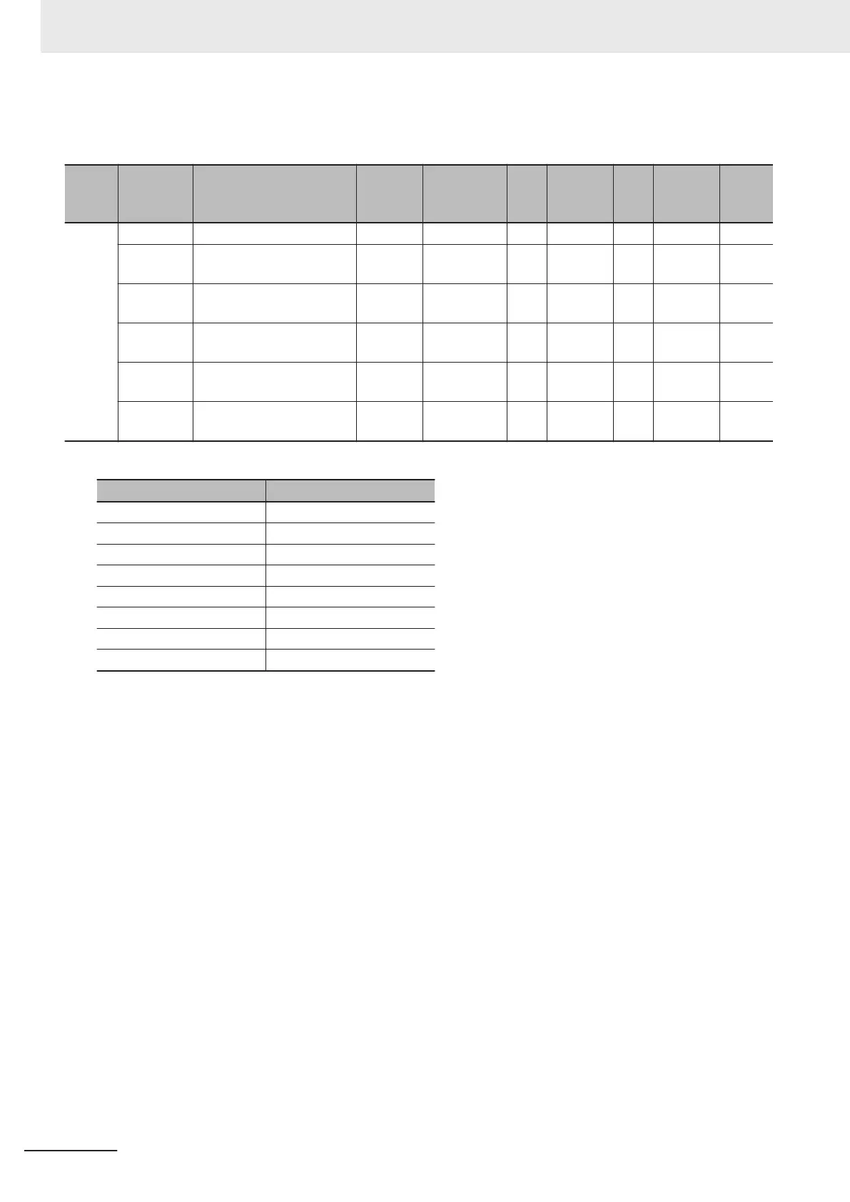
5009 --- Trigger Input Filter Setting --- --- --- --- --- --- ---
00 Number of Entries 4 4 --- USINT RO Not pos-
sible
---
01 Ch1 Input Filter Value Set-
ting
4
0, or 3 to 9
*1
--- USINT R/W Not pos-
sible
N
02 Ch2 Input Filter Value Set-
ting
4
0, or 3 to 9
*1
--- USINT R/W Not pos-
sible
N
03 Ch3 Input Filter Value Set-
ting
4
0, or 3 to 9
*1
--- USINT R/W Not pos-
sible
N
04 Ch4 Input Filter Value Set-
ting
4
0, or 3 to 9
*1
--- USINT R/W Not pos-
sible
N
*1.
The meanings of the set values for Ch£ Input Filter Value Setting are as follows.
Set value Meaning
0 No Filter
3 4 µs
4 8 µs
5 16 µs
6 32 µs
7 64 µs
8 128 µs
9 256 µs
• Refer to 8-11 Input Filter on page 8 - 48 for details on the function.
Appendices
A - 50
NX-series Analog I/O Units User’s Manual for High-speed Analog Input Units (W592)