AND
BEARING
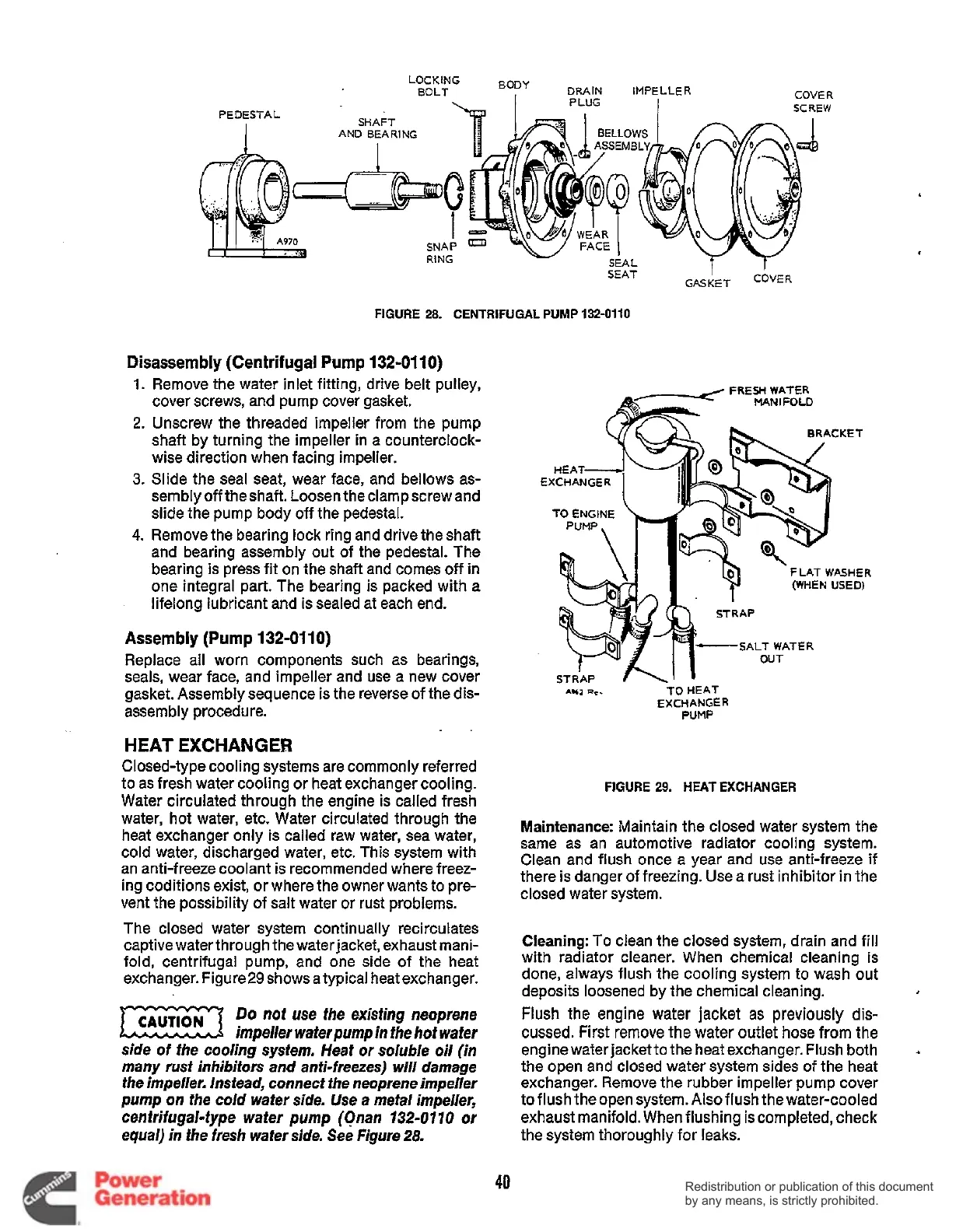
FIGURE 28. CENTRIFUGAL PUMP 132-0110
Disassembly (Centrifugal
Pump 132-01
10)
1.
Remove the water inlet fitting, drive belt pulley,
FRESH WATER
MAN
I
FOLD
cover screws, and pump cover gasket.
2.
Unscrew the threaded impeller from the pump
shaft by turning the impeller in a counterclock-
wise direction when facing impeller.
3.
Slide the seal seat, wear face, and bellows as-
semblyofftheshaft. Loosentheclampscrew and
slide the pump body
off
the pedestal.
4.
Remove the bearing lock ring and drive the shaft
and bearing assembly out of the pedestal. The
lifelong lubricant and is sealed at each end.
E
bearing is press fit on the shaft and comes
off
in
one integral part. The bearing is packed with a
FLAT WASHER
(WHEN
USED)
Assembly
(Pump 132-0110)
SALT WATER
Replace all worn components such as bearings,
seals, wear face, and impeller and use a new cover
gasket. Assembly sequence is the reverse of the dis-
TO
HEAT
EXCHANGER
assembly procedure.
PUMP
HEAT
EXCHANGER
Closed-type cooling systems are commonly referred
to as fresh water cooling or heat exchanger cooling.
Water circulated throuah the enaine
is
called fresh
FIGURE
29.
HEAT EXCHANGER
water, hot water, etc. fiater circilated through
the
heat exchanger only is called raw water, sea water,
cold water, discharged water, etc. This system with
an anti-freeze coolant is recommended where freez-
ing coditions exist, or where the owner wants to pre-
vent the possibility of salt water or rust problems.
Maintenance: Maintain the closed
water
system the
Same
as
an
automotive
radiator
cooling
system.
Clean and flush
Once
a
year and
use
anti-freeze
if
there
is
danger
of
freezing.
Use
a rust
inhibitor
in
the
closed
water
system.
The closed water system continually recirculates
captive water through the waterjacket, exhaust mani-
fold, centrifugal pump, and one side of the heat
exchanger. Figure29 shows a typical heat exchanger.
Cleaning:
To
clean the closed system, drain and fill
with radiator Cleaner. When chemical Cleaning
iS
done, always flush the cooling system to wash out
deposits loosened by the chemical cleaning.
Do
nof use the exisfing neoprene
impeller waferpump in fhe hof wafer
side of the cooling system. Heat or soluble oil (in
many rust inhibitors and anti-freezes) will damage
the impeller. Instead, connect the neoprene impeller
pump on the cold wafer side. Use a metal impeller,
cenfrifugal-type wafer pump (Onan
732-07
70
or
equal) in ihe fresh wafer side. See Figure
28.
Flush
the engine water jacket
as
previously
dis-
cussed. First remove
the
water outlet hose from the
engine water jacket to the heat exchanger. Flush both
the open and closed water system sides of the heat
exchanger. Remove the rubber impeller pump cover
to flush theopen system.
Also
flush thewater-cooled
exhaust manifold. When flushing
is
completed, check
the system thoroughly for leaks.
.
40
Redistribution or publication of this document
by any means, is strictly prohibited.
Redistribution or publication of this document
by any means, is strictly prohibited.
 Loading...


