2-6 Identifying the Internal Components
Legacy USB speeds such as Full-Speed (FS) and Low-Speed (LS) are handled by the USB
2.0 controller. The SuperSpeed USB 3.0 Controller operates in parallel with the USB 2.0
controller so that the SuperSpeed data transfers are not affected by USB 2.0 traffic.
Four downstream USB 3.0 SuperSpeed Ports. On the E-Series Main Board, each
port is connected to the following:
– SS Ports 1 (USB3_1) and 2 (USB3_2) are fed directly to CN3A and CN3B and
designated USB3 and USB4 on the I/O Panel. The blue connectors indicate
USB 3.0 compatibility.
– SS Port 3 (USB3_3) is fed to U40, an on-board AX88179 USB 3.0 to Gigabit
Ethernet Controller. U40 is a highly integrated ASIC, combining a USB 3.0
PHY and 10/100/1000Mbps Gigabit Ethernet PHY in a single package. The
Ethernet PHY supports IEEE 802.3, IEEE 802.3u and IEEE 802.3ab. The
output is fed to I/O Panel connector U6 for wired Ethernet.
– SS Port 4 is configured for USB 2.0 operation and fed to the 2x5 header J3 for
Protégé Customer Display support. The USB 3.0 interface is not used.
Three downstream USB 2.0 ports labeled HS5, HS6, and HS7.
– HS5 is fed to U30, a USB2513 USB 2.0 compatible 4-Port Hub.
– HS6 is fed to U6, a USB to 4-Port Serial UART.
– HS7 is fed to U31 a USB to 2-Port Serial UART.
USB 3.0 Overview
The USB 3.0 specification improves upon the USB 2.0 specification by adding a physically
separate full-duplex (two ways) communications channel on top of the existing half
duplex (one way) USB 2.0 channel.
USB 3.0 introduces a new 5 Gbit/s transfer type called SuperSpeed or ‘SS’ where one
channel is dedicated to transmitting data and the second channel dedicated to receiving
data simultaneously. This eliminates the overhead associated with a USB 2.0 controller
having to ‘turn-around’ the half duplex channel from transmit to receive and vise-versa.
U65 or any USB hub supporting both specifications will include independent USB
controllers to prevent USB 2.0 data transfers from interfering with USB 3.0 data transfers.
USB 3.0 Type A Plugs and Receptacles
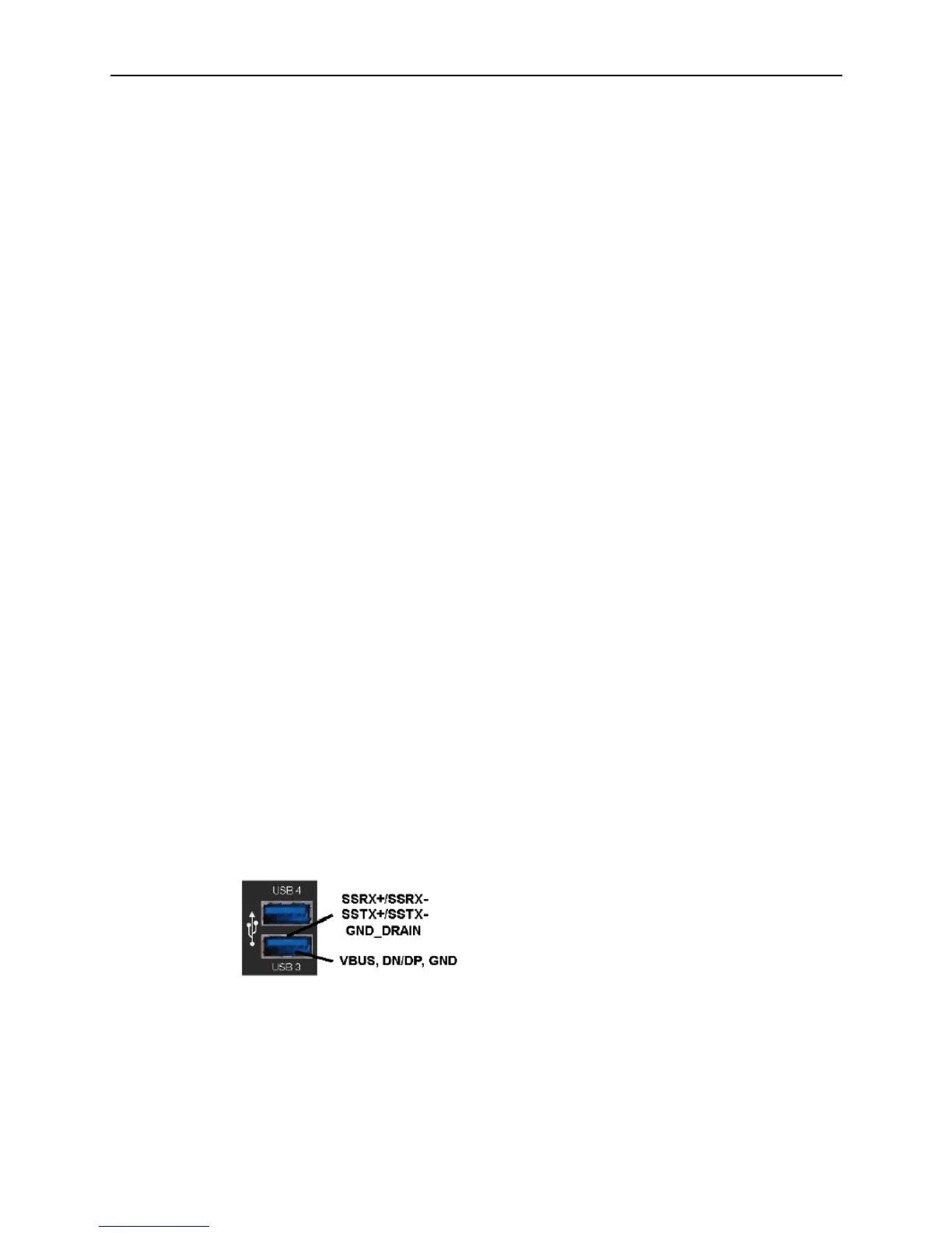
The figure below shows a typical USB 3.0 Type A receptacle on the Base Station E-Series.
USB 3.0 adds five more pins to the existing Type A Plug and Receptacles and are colored
blue. The existing USB 1.x/2.0 compatible pins are at the lower half labeled VBUS
(Power), DN/DP, and GND.
Figure 2-7 Typical USB 3.0 Type A Receptacle
USB 3.0 adds 5 pins to the upper half of the connector, including two differential pairs for
SuperSpeed signaling, called out as SSRX+/SSRX- and SSTX+/SSTX- and GND_DRAIN
in the figure above. The additional ground wire is critical for maintaining the
SuperSpeed channel signal integrity and reducing EMI.