EasyManua.ls Logo

Oracle e-series User Manual

Default Icon
82 pages
To Next Page IconTo Next Page
To Previous Page IconTo Previous Page
Page #79 background image
Appendix B B-1
Appendix B: Connector and Cable
Diagrams
This appendix provides an overview of the connectors and cables used to hook-up your
POS equipment.
I/O Panel Connectors
The following connectors are located on the Base Station I/O Panel.
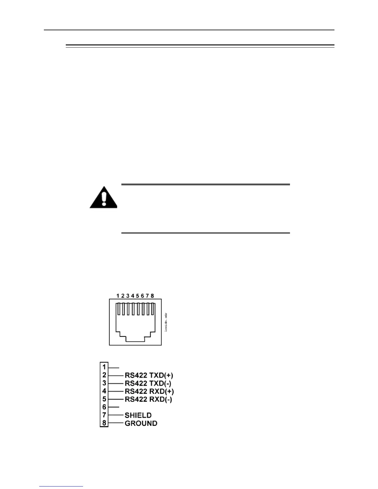
IDN Port
The IDN connector is a combination RS422/RS232 port assigned to COM4. This port is
functionally equivalent to the RS422-A and RS422-B ports on the WS4/WS4 LX/KWS4
and the IDN port on all current MICROS workstations. Two configurations are detailed
in the following pages, configured through the POS application.
Warning: Do not insert a 6-Pin modular plug into the 8-Pin
IDN Port. The 6-Pin plug can push pins 1 and 8 of the
connector out of position. These pins are used by the RS232
Interface. Should you wish to use the RS232 Interface at a
later time, it may not function. Always use an 8-Pin modular
plug to connect an IDN printer to the workstation.
IDN Port - Driving MICROS IDN Printers
The most popular configuration of the IDN Port is for printing to printers with IDN
Modules. Also known as IDN(+), the figure below shows the pin-out for this
configuration.

Table of Contents

Question and Answer IconNeed help?

Do you have a question about the Oracle e-series and is the answer not in the manual?

Oracle e-series Specifications

General IconGeneral
BrandOracle
Modele-series
CategoryTablet
LanguageEnglish

Summary

Preface and Support Information

Audience and Documentation

Defines the intended users and provides links to Oracle Hospitality product documentation.

Customer Support and Revision History

Provides contact details for Oracle Customer Support and lists document revision history.

Introduction to MICROS Tablet and Base Station E-Series

Tablet E-Series Overview and Features

Details the two Tablet E-Series models (8" and 11"), their features, and optional MSR sleeves.

Base Station E-Series Functionality and Peripherals

Explains the Base Station's role, connectivity, indicators, and supported accessories.

System Specifications and Certifications

Provides detailed specifications for Tablet E-Series, Base Station, power, and certifications.

Identifying the Internal Components

Base Station E-Series Disassembly and Main Board

Procedure for disassembling the Base Station and description of its main board components and block diagram.

Base Station E-Series Controllers and ICs

Details the MCU, USB hubs, UARTs, fuel gauge, and charger ICs on the Base Station E-Series main board.

Installing and Operating the Tablet and Base Station E-Series

Environment, Care, and Safety Precautions

Covers equipment placement, handling, ESD, operating temperatures, and proximity to foreign materials.

Tablet E-Series Operation, Controls, and Settings

Details basic operation, operator controls, power settings, touchscreen calibration, and MSR sleeve installation.

Tablet E-Series Recovery and Charging

Covers charging procedures, recovery methods, and creating/using recovery flash drives.

Base Station Operation and Peripherals Installation

Details Base Station operation, tray, LEDs, battery, docking, storage, warnings, and installation of peripherals.

Tablet and Base Station E-Series Diagnostics Utilities

Starting Diagnostics Utility and System Information

Instructions on starting the utility and viewing system and battery information.

Device-Specific Diagnostic Tests

Covers tests for customer displays, cash drawers, serial ports, battery, scanner, printer, and LEDs.

Appendices: Dimensions and Connectors

Equipment Dimensions

Provides dimensional drawings for tablets, base stations, and accessories.

Connector and Cable Diagrams

Details I/O panel connectors, including IDN, RS232, and Cash Drawer connections.

Related product manuals