Installing and Operating the Tablet and Base Station E-Series 3-23
5. Remove the AC Power from the Base Station, and then connect the keyed 4-pin DIN
connector to the port labeled Customer Display.
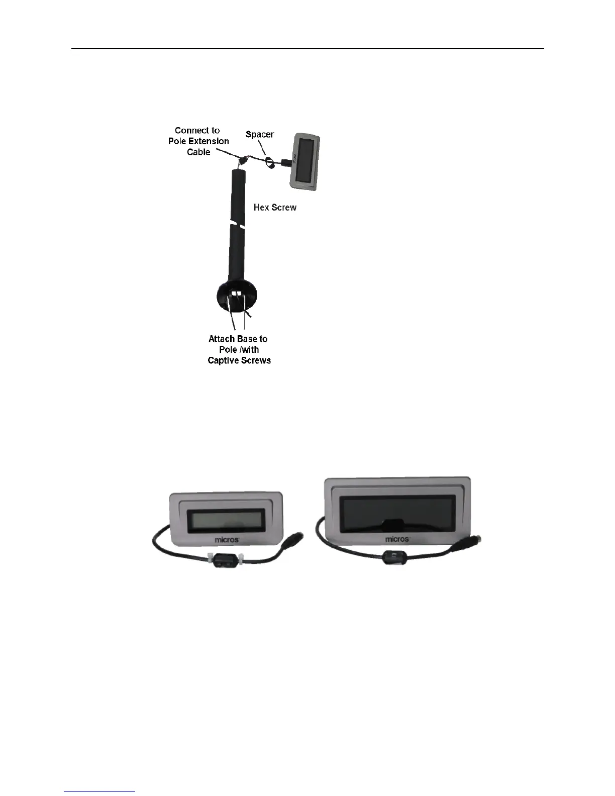
Figure 3-23 Assembling the Series 2 Pole Display
Installing the Series 2 Integrated Customer Displays
The Series 2 Integrated 2x20 LCD (left) and the 240x64 LCD (right) are shown below. The
Series 2 Customer Displays, introduced with the Base Station R-Series, share an
integrated mounting bracket, interface cable, and installation procedure. Each display is
compatible with both the Base Station R-Series and Base Station E-Series.
Figure 3-24 Series 2 Integrated Customer Displays
The following procedure applies to the 2x20 Text LCD or 240x64 Graphics LCD Displays
as well as the Base Station R-Series and Base Station E-Series.
1. Before installing any Base Station peripheral, remove the Tablet and the AC power
cable. If the optional Smart Battery is installed, remove it as well.
2. Place the Base Station E-Series facedown and locate the accessory mounting holes at
the rear of the base.
3. Attach the Series 2 Customer Display bracket, and then turn the thumbscrews to
secure the bracket to the base.