6-34
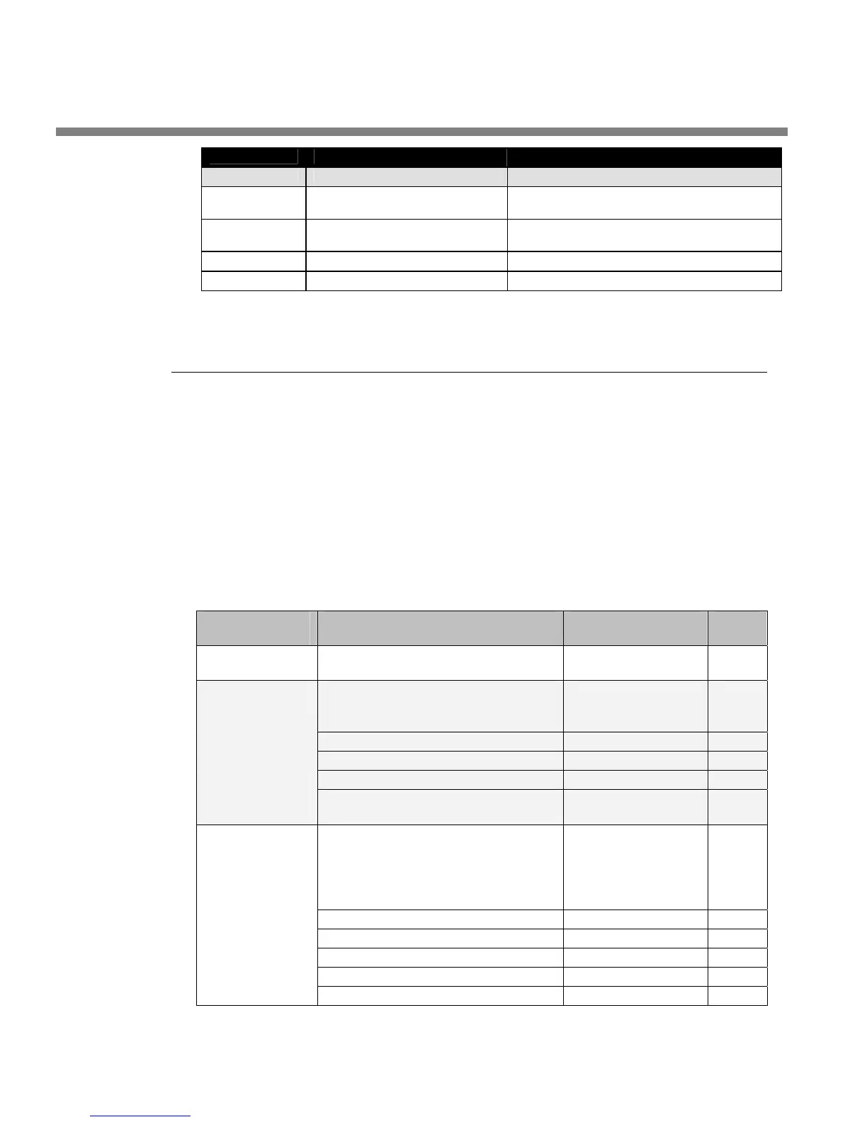
TECHNICAL DATA ORBAN MODEL 8685
SERIAL BOARD for SDI OPTION
PART # DESCRIPTION COMPONENT IDENTIFIER
27421.050.01.1
Connector Header STR .23
2X25
J100
21141.000.01.1
Capacitor NPO 1000PF 1%
0805
C102
20132.100.01.1 Resistor 1/8W 1% 100K R0805 R102
20130.100.01.1 Resistor 1.00K 1% 0805 R100, R101
Schematics and Parts Locator Drawings
These drawings reflect the actual construction of your unit as accurately as possible.
Any differences between the drawings and your unit are probably due to product
improvements or production changes since the publication of this manual.
If you intend to replace parts, please read page 6-15. Please note that because sur-
face-mount parts are used extensively in the 8500, few parts
are field-replaceable.
Servicing ordinarily occurs by swapping circuit board assemblies. However, many
vulnerable parts connected to the outside world are socketed and can be readily re-
placed in the field.
Because the drawings are based on vectors and not bitmaps, they can be magnified
as needed to make fine print legible.
Function Description Drawing Page
Chassis
Circuit Board Locator and basic
interconnections
Top view
(not to scale)
6-37
Base Board
Glue logic; supports CPU module
and RS-232 daughterboard.
Contains:
Parts Locator
Drawing
6-38
System Connections Schematic 1 of 4
6-39
CPU module interface Schematic 2 of 4
6-40
Power Supply Monitor Schematic 3 of 4
6-41
CPLD, General Purpose Interface,
and Remotes
Schematic 4 of 4
6-42
CPU Module
Control microprocessor. Services
front panel, serial port, Ethernet,
DSP board, and control board. Re-
sides on base board.
Contains:
Parts Locator
Drawing
6-43
Ethernet Schematic 1 of 5
6-44
General Purpose Bus Schematic 2 of 5
6-45
Memory Schematic 3 of 5
6-46
Miscellaneous Functions Schematic 4 of 5
6-47
Power and Ground Distribution Schematic 5 of 5
6-48