2-8
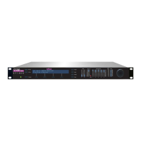
INSTALLATION ORBAN MODEL 8685
• If an unbalanced output is required (to drive unbalanced inputs of other equip-
ment), it should be taken between pin 2 and pin 3 of the XLR-type connector.
Connect the L
OW pin of the XLR-type connector (#3 or #2, depending on your
organization’s standards) to ground; take the H
IGH output from the remaining
pin. No special precautions are required even though one side of the output is
grounded.
• At the 8685’s output (and at the output of other equipment in the system), do
not connect the cable’s shield to the CHASSIS GROUND terminal (pin 1) on the
XLR-type connector. Instead, connect the shield to the chassis ground at the in-
put destination. Connect the red (or white) wire to the pin on the XLR-type con-
nector (#2 or #3) that is considered H
IGH by the standards of your organization.
Connect the black wire to the pin on the XLR-type connector (#3 or #2) that is
considered L
OW by the standards of your organization.
Power Ground
• Ground the 8685 chassis through the third wire in the power cord. Proper
grounding techniques never leave equipment chassis unconnected to
power/earth ground. A proper power ground is essential for safe operation. Lift-
ing a chassis from power ground creates a potential safety hazard.
Quick Setup
The 8685’s Quick Setup feature provides a guided, systematic procedure for setting
up the 8685. It should be adequate for most users without special or esoteric re-
quirements. Following this section, you can find more detailed information regard-
ing setup outside the Quick Setup screens. Mostly, you will not need this extra in-
formation.
For the following adjustments, use L
OCATE (the green joystick, between ESCAPE and
E
NTER) to select parameters. After you have highlighted the desired parameter on
the screen, use the front panel control knob to adjust the parameter settings as de-
sired.
• The 8685 has input and output routing switchers that connect the 8685’s physical
inputs and output to the logical inputs and outputs of the 8685’s 7.1 surround
and four 2.0 audio processors, all of which are active simultaneously. (If you are
processing 5.1 surround, do not feed program material to the Lb and Rb inputs
of the surround processor.)
Quick Setup allows you to retain a custom routing setup or to use the factory de-
fault. In the base unit AES3id input #1=Lf/Rf, #2=C/LFE, #3= Ls/Rs, #4=Lb/Rb (ap-
plies to 7.1 processing only), and #5=Stereo (2.0 processor #1). This arrangement
is consistent with the Dolby DP-569 Dolby Digital Encoder’s default I/O routing
setting and with ATSC A/54A.

 Loading...