OPTIMOD MAINTENANCE
4-11
Test Procedure for the Base I/O Module
If you have an 8685 with the base I/O module (no HD-SDI), follow steps 4 through 9
below.
4. Test Digital I/O and Sync for Input/Output 1/2 (Lf/Rf).
A) Recall the A
UDIT3 Setup. This uses the 2.0 processing chain as a test tone gen-
erator to test the surround channels.
B) Using a 75Ω BNC/BNC jumper cable, the 8685’s O
UTPUT 11/12 BNC connector to
its I
NPUT 1/2 BNC connector and verify that the 1/2 indicator on the 8685’s
front panel turns yellow, indicating that the 8685’s
INPUT 1/2 AES3id receiver
has locked to the signal emitted from O
UTPUT 11/12.
C) Connect the digital analyzer to the 8685’s O
UTPUT1/2 BNC connector and verify
that the THD+N is below –100 dBfs and that the sample rate is 48 kHz, as
locked to the input sample rate.
D) A
UDIT3 emits its test signal at a 48 kHz sample rate. To test 32 kHz, 44.1 kHz,
88.2 kHz, and 96 kHz sample rates, recall
AUDIT4, AUDIT5, AUDIT6, and AUDIT7 in
turn. Use the AES3id analyzer to do the following for each sample rate:
a) Measure the THD+N and verify that it is below –100 dBfs (0.001%).
b) Listen to the AES3id analyzer’s decoded analog output and verify that the
output sounds clean and glitch-free.
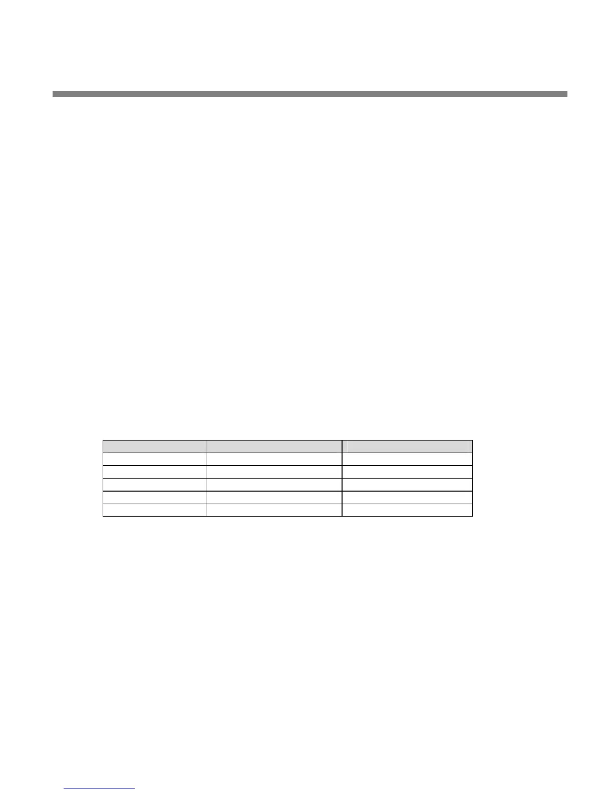
c) Verify that the frequencies measured at the 8685’s O
UTPUT 1/2 follow the
values in the chart below within given tolerances.
Sample Rate Tolerance (PPM) Tolerance ( Hz)
32.0 kHz 100 PPM ±3.20 Hz
44.1 kHz 100 PPM ±4.41 Hz
48.0 kHz 100 PPM ±4.80 Hz
88.2 kHz 100 PPM ±8.82 Hz
96.0 kHz 100 PPM ±9.60 Hz
Table 4-4: Frequency Tolerance for Various Sample Rates
5. Test Digital I/O and Sync for Input/Output 3/4 (C/LFE).
Connect the 8685’s O
UTPUT 11/12 BNC connector to its INPUT 3/4 BNC connector,
connect the analyzer to O
UTPUT 3/4, and follow the procedure in step 4 by anal-
ogy. Use Setups A
UDIT8 through AUDIT12.
6. Test Digital I/O and Sync for Input/Output 5/6 (Ls/Rs).
Connect the 8685’s O
UTPUT 11/12 BNC connector to its INPUT 5/6 BNC connector,
connect the analyzer to O
UTPUT 5/6, and follow the procedure in step 4 by anal-
ogy. Use Setups A
UDIT13 through AUDIT17.