2-4
INSTALLATION ORBAN MODEL 8685
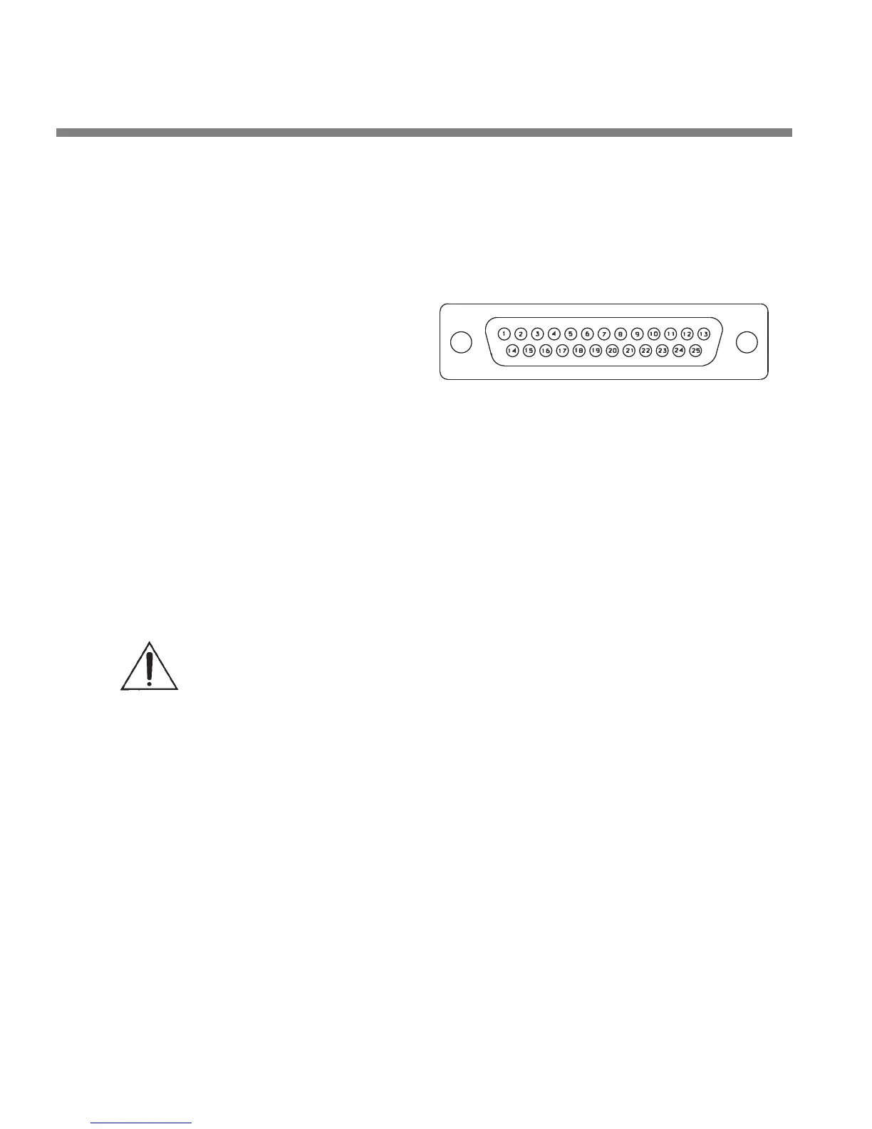
PIN ASSIGNMENT
1. COMMON
2. REMOTE 1+
3. REMOTE 2+
4. REMOTE 3+
5. REMOTE 4+
6. REMOTE 5+
7. REMOTE 6+
8. REMOTE 7+
9. REMOTE 8+
10. TALLY 1
11. TALLY 2
12. N/C
13. POWER COMMON
14. REMOTE 1-
15. REMOTE 2-
16. REMOTE 3-
17. REMOTE 4-
18. REMOTE 5-
19. REMOTE 6-
20. REMOTE 7-
21. REMOTE 8-
22-24. N/C
25. +12 VOLTS DC
REMOTE INTERFACE
Figure 2-2: Wiring the 25-pin Remote Interface Connector
The tally outputs are protected against reverse polarity.
To avoid damaging the 8685, limit the current into a tally output to
30 mA. DO NOT connect a tally output directly to a low-impedance volt-
age source! The tally outputs are not protected against this abuse and the
output transistors are likely to burn out. When driving a relay or other in-
ductive load, connect a diode in reverse polarity across the relay coil to
protect the driver transistors from reverse voltage caused by inductive
kickback.
Note that the tally outputs have no special RFI protection. Therefore, it is wise to
use shielded cable to make connections to them.
See step 22 on page 2-37 for instructions on programming the tally outputs.
7. Connec
t to a computer
You can connect to a computer via the 8685’s serial connector or via an Ethernet
network. See Networking and Remote Control on page 2-56 and Installing 8685
PC Remote Control Software on page 2-62 for more details.