Preparation
20
Safety precautions How to use Help Appendix
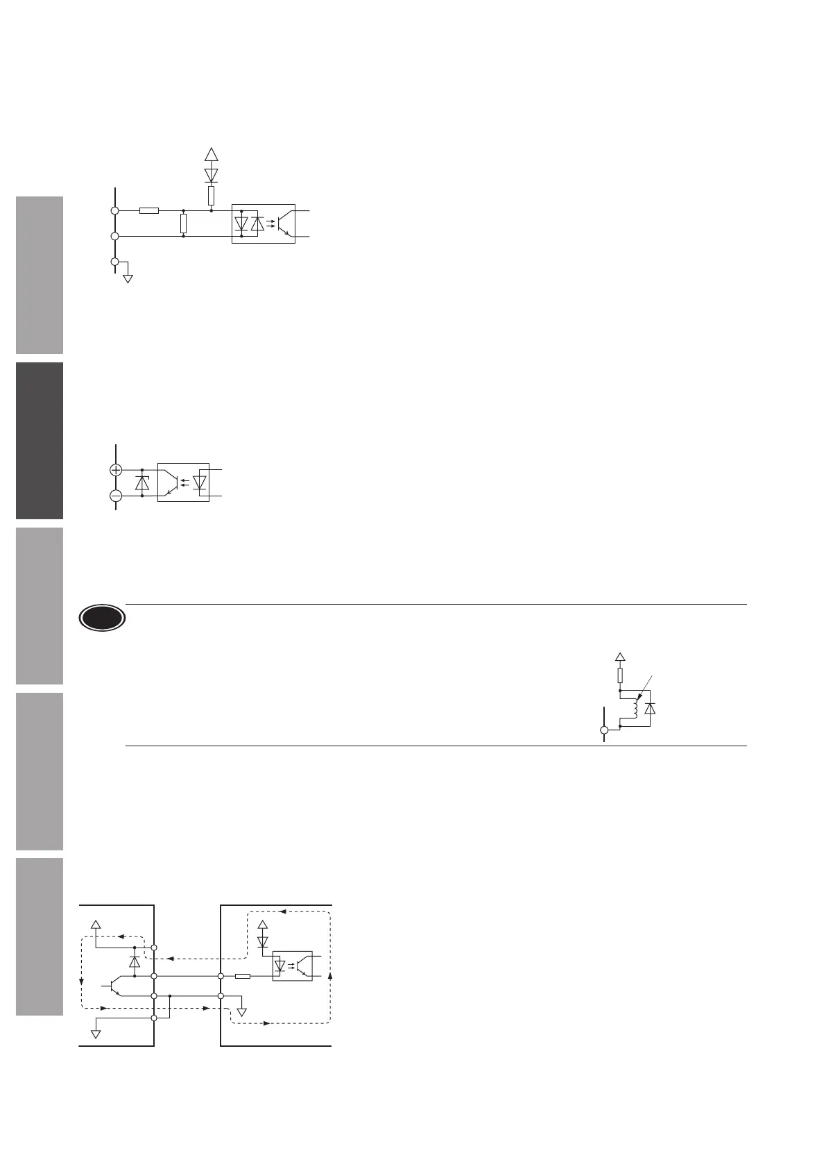
Input signals circuit
All input signals of the driver are photocoupler inputs.
When an external power supply is used: 20.4 to 28.8 VDC, 100 mA or more
1 kΩ
6.6 kΩ
680 Ω
9
1
in No.
Photocoupler
2 to 8
+5 V
z
Changing the logic level setting of input signals
The logic level setting for input terminals IN0 to IN6 can be changed using the
MEXE02
or operation panel.
Refer to p.65 for details.
Output signals circuit
All output signals of the driver are photocoupler/open-collector outputs.
ON voltage: 1.6 VDC maximum
External power supply: 4.5 to 30 VDC, 100 mA or less (5 mA or more for the SPEED-OUT output)
z
Changing the logic level setting of output signals
The logic level setting for output terminals OUT0 and OUT1 can be changed using the
MEXE02
or operation panel.
However, if the SPEED-OUT output is assigned, it cannot be changed.
Refer to p.65 for details.
Note
•
For output signals, be sure to connect a current-limiting resistor so that the current does not exceed 100 mA.
When using a programmable controller, check the resistance value inside the controller and connect a current-
limiting resistor as necessary.
•
When connecting a relay (inductive load), etc., to detect alarm outputs, provide
a y-back voltage control measure based on diode, etc., for the inductive load.
Or use a relay with built-in ywheel diode.
15, 17
in No.
Inductive load
Fly
When using a controller with a built-in clamp diode
If a controller with a built-in clamp diode is used, a leakage path may form and cause the motor to rotate even when the
controller power is turned o, as long as the driver power is on.
Since the current capacity of the controller is dierent from that of the driver, the motor may rotate when the controller and
driver powers are turned on or o simultaneously.
When powering down, turn o the driver power rst, followed by the controller power, and when powering up, turn on the
controller power rst, followed by the driver power.
equipment
Driver
2 to 8
9
CN5
VCC +5 V
0 V
0 V
 Loading...