Appendix
83
HelpHow to usePreparationSafety precautions
5. Conformity to the EMC
Eective measures must be taken against the EMI that the motor and driver may give to adjacent controlsystem equipment, as
well as the EMS of the motor and driver itself, in order to prevent a serious functional impediment in the machinery. The use of
the following installation and wiring methods will enable the motor and driver to be compliant with the EMC.
Oriental Motor conducts EMC testing on its motors and driver in accordance with “Example of installation and wiring” on p.84.
The user is responsible for ensuring the machine’s compliance with the EMC, based on the installation and wiring explained
below.
This equipment is not intended for use in residential environments nor for use on a lowvoltage
public network supplied in residential premises, and it may not provide adequate protection to
radio reception interference in such environments.
Connecting a mains lter
Install a mains lter which the customer provides, in the power line in order to prevent the noise generated within the driver from
propagating outside via the AC input line. For a mains lter, use the products as shown in the table, or an equivalent.
Manufacturer
Single-phase 100-120 VAC
Single-phase 200-240 VAC
Three-phase 200-240 VAC
Soshin Electric Co., Ltd. HF2010A-UPF, NF2010A-UP HF3010C-SZA, NFU3010C-Z1
Schaner EMC FN2070-10-06 FN3025HP-10-71
•
Overvoltage category II applies to mains lters.
•
Install the mains lter as close to the driver as possible.
•
Use cable clamps and other means to secure the input and output cables rmly to the surface of the enclosure.
•
Connect the ground terminal of the mains lter to the grounding point, using as thick and short a wire as possible.
•
Do not place the AC input cable (AWG18 to 14: 0.75 to 2.0 mm
2
) parallel with the mains-lter output cable (AWG18 to 14: 0.75
to 2.0 mm
2
). Parallel placement will reduce mains lter eectiveness if the enclosure’s internal noise is directly coupled to the
power supply cable by means of stray capacitance.
Connecting an external power supply
Use an external power supply conforming to the EMC. Use a shielded cable to wire the external power supply over the shortest
possible distance. Refer to "Wiring the power supply cable" for how to ground the shielded cable.
How to ground
The cable used to ground the motor, driver, mains lter and power supply cable (shielded cable) must be as thick and short
as possible so that no potential dierence is generated among the grounding points. Choose a large, thick and uniformly
conductive surface for the grounding point. Refer to the p.18 for the recommended grounding method.
Wiring of the power supply cable
Use a shielded cable of AWG18 to 14 (0.75 to 2.0 mm
2
) in diameter for the power supply cable and keep it as short as possible.
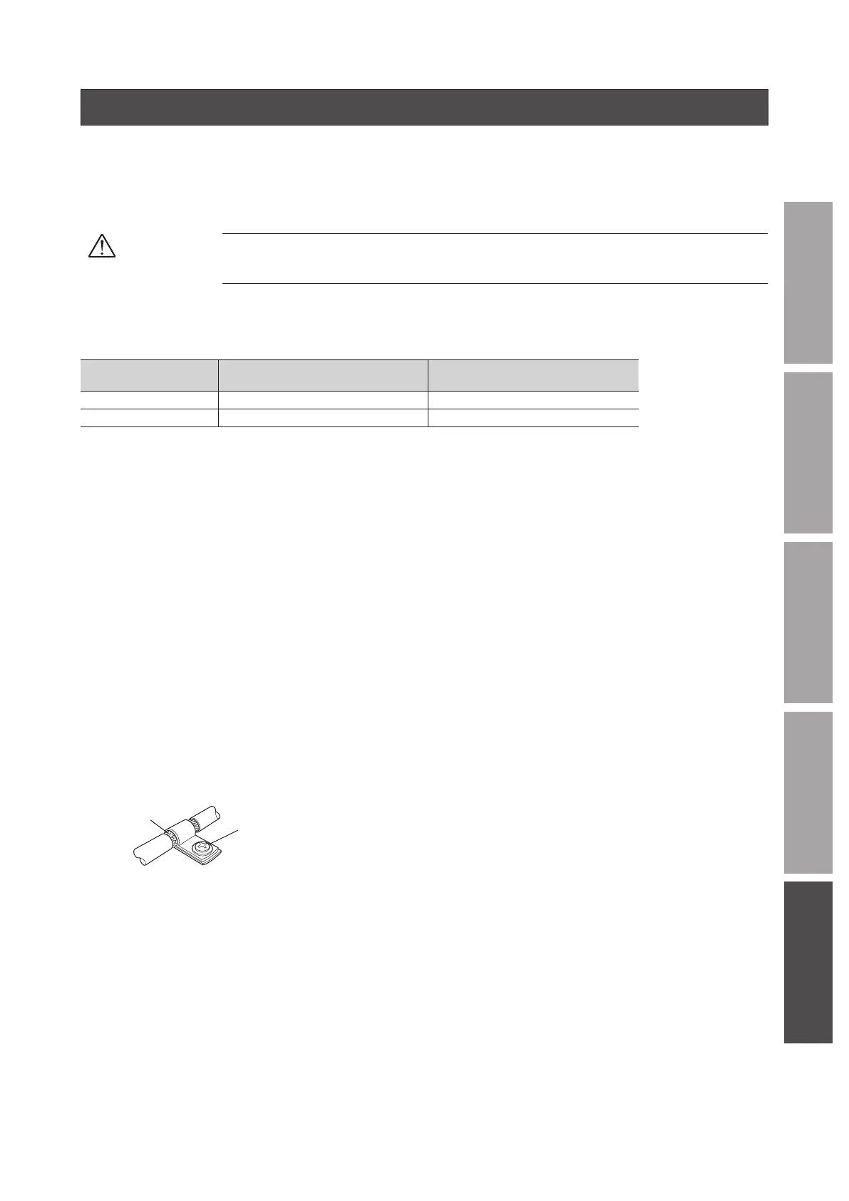
Strip a part of the shielded cable and ground the stripped part using a metal cable clamp that contacts the stripped cable around
its entire circumference, or use a drain wire to make the ground connection.
Connect both ends (mains lter side and power supply side) of the shielded cable to the grounding points so that no potential
dierence is generated between grounds.
Cable clamp
Shielded cable
Notes about installation and wiring
•
Connect the motor, driver and other peripheral control equipment directly to the grounding point so as to prevent a potential
dierence from developing between grounds.
•
When relays or electromagnetic switches are used together with the product, use mains lters or CR circuits to suppress surges
generated by them.
•
Keep cables as short as possible without coiling and bundling extra lengths.
•
Wire the power lines such as the connection cable and power supply cable away from the signal cables by providing a minimum
clearance of 100 mm (3.94 in.) between them. If they must cross, do so at a right angle.
Place the AC input cable and output cable of a mains lter separately from each other.
•
Use a dedicated connection cable (sold separately) for the connection between the motor and driver.
The EMC measures are conducted using the Oriental Motor connection cable.