How to use
39
PreparationSafety precautions Help Appendix
2-4 Operation/standstill using external signals
To switch between operation and stop of the motor in the 2-wire mode, the FWD input and the REV input are used.
This section explains as an example when the “2-Wire mode 1" is selected with the "Operation input mode selection" parameter.
Refer to p.64 for the operation input mode.
FWD input REV input Motor movement
Turn the input signal having
turned ON to OFF
*
ON OFF Rotates in the forward direction Deceleration stop
OFF ON Rotates in the reverse direction Deceleration stop
Turn both signals ON during rotation Deceleration stop –
*
How to stop the motor can be changed by the setting of the STOP-MODE input.
STOP-MODE input OFF ON
Stopping movement Deceleration stop Instantaneous stop
Note
When the electromagnetic brake motor is used in an application of vertical drive such as elevating equipment,
although depending on a load condition, the motor shaft rotation may momentarily reverse (within 90 degrees of the
motor output shaft) at the time of starting or stopping if it is operated under the setting conditions below.
• When the set rotation speed is low
• When the acceleration time or deceleration time is long
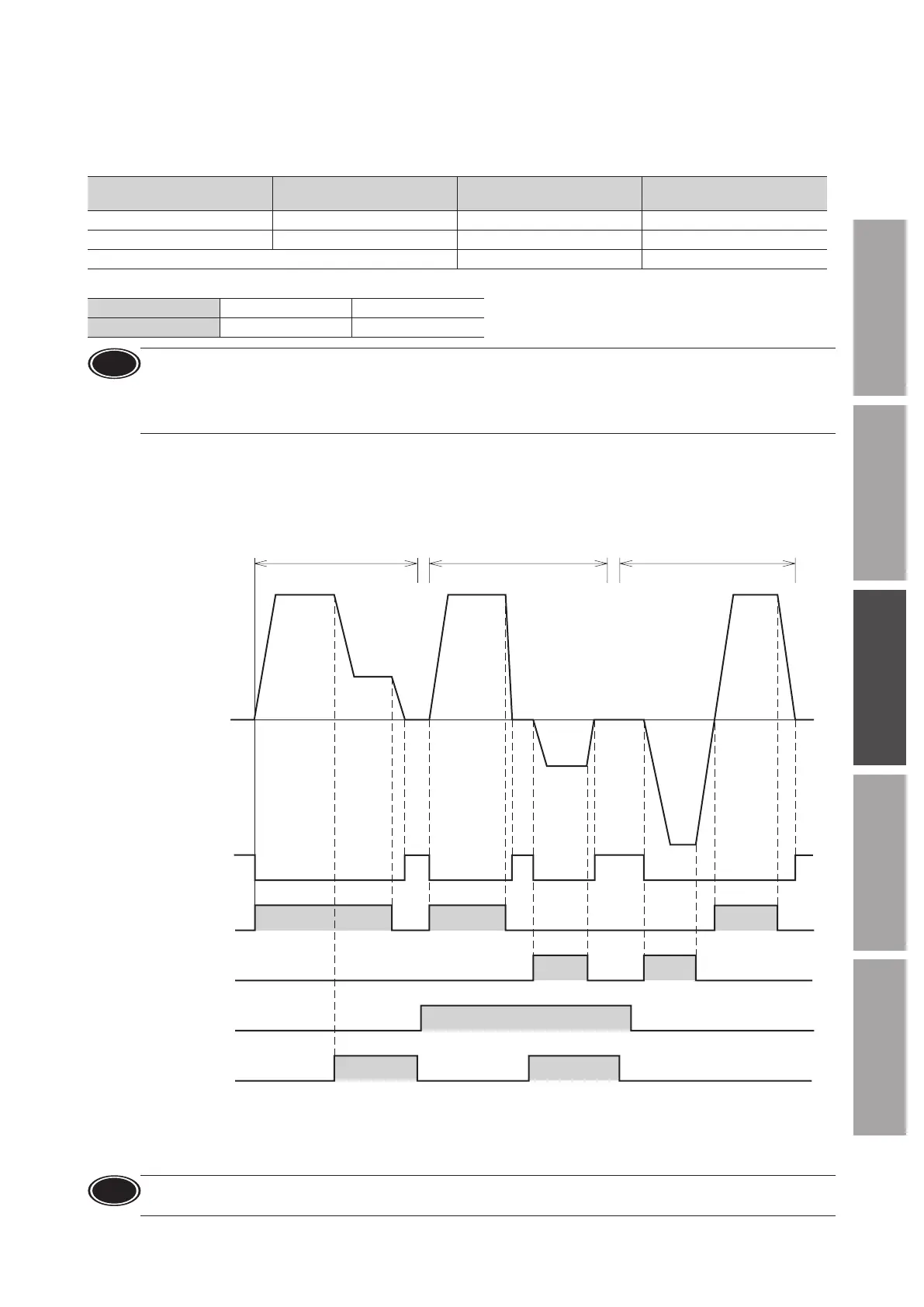
Operation example
The chart below is an example when the operation data No.0 and No.1 are set to 3000 r/min and 1000 r/min respectively, and the
speed of the electromagnetic brake motor is switched between these two levels.
Refer to p.44 for the setting and operation when operating at two or more speeds.
Switching between two speed levels,
Deceleration stop
3000 r/min
1000 r/min
Run, Instantaneous stop Rotation direction switching ∗
CW CW
CCW
CW
CCW
Hold
Release
OFF
ON
Motor operation
FWD input
REV input
M0 input
ON
OFF
ON
ON
OFF
No.0 No.1 No.1No.0 No.0
Electromagnetic
brake operation
*
When the motor is combined with the
JH
gearhead,
JB
gearhead, or
JV
gearhead, the rotation direction cannot be switched
instantaneously depending on the motor output. Check the operating manual of the motor.
•
The motor rotation direction can be switched by setting of the “Motor rotation direction” parameter.
This example shows when “Positive direction=CW” is set.
Note
•
Make sure each signal remains ON for at least 10 ms.
•
When switching the motor rotation direction, provide an interval of at least 10 ms to turn the signal ON.