Preparation
30
Safety precautions How to use Help Appendix
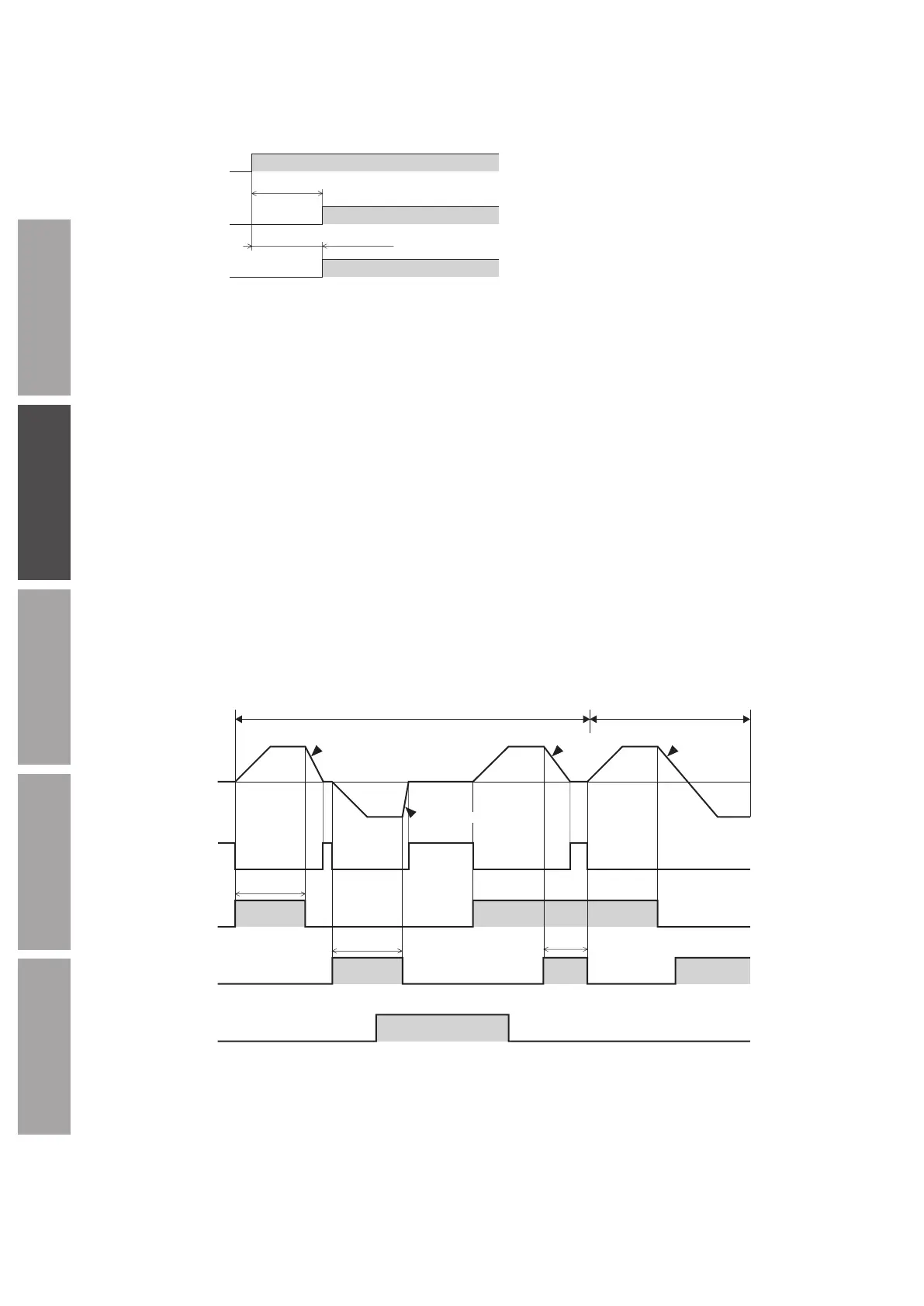
9-2 Timing chart when power is input
This timing chart describes the timing of input signals and output signals when the power supply is turned on.
Signal is output
OFF
ON
OFF
Output signal
0.5 s or less
0.5 s or more
Input enabled
ON
Input signal
9-3 Description of input signals
Operation input signals vary depending on the input mode. The input mode can be changed by the setting of the "Operation
input mode selection" parameter (ID: 1819). Refer to p.64 for details.
Operation input signals
2-Wire mode: FWD input, REV input, STOP-MODE input
3-Wire mode: START/STOP input, RUN/BRAKE input, CW/CCW input
2-Wire mode
z
FWD input, REV input
When the FWD input is turned ON, the motor rotates in the forward direction. The motor decelerates to a stop when the signal is
turned OFF.
When the REV input is turned ON, the motor rotates in the reverse direction. The motor decelerates to a stop when the signal is
turned OFF.
The chart below shows an example when the "Motor rotation direction" parameter (ID: 450) is set to “Positive direction=CW.”
If the "Operation input mode selection" parameter (ID: 1819) is set to "2-Wire mode 1,” the motor decelerates to a stop when both
the FWD input and the REV input are turned ON.
z
STOP-MODE input
This is a signal to select how the motor would stop when the FWD input or the REV input is turned OFF.
When the STOP-MODE input is OFF, the motor decelerates to a stop according to the deceleration time of the operation data
number.
When the STOP-MODE input is ON, the motor stops at the shortest time (instantaneous stop).
10 ms or more
10 ms or more
10 ms or more
Motor operation
CCW
CW CW CW
CCW
FWD input
OFF
ON
REV input
ON
OFF
STOP-MODE input
ON
OFF
Forward and reverse operation
Deceleration
stop
Rotation direction switching/Stop mode selection
Deceleration
stop
Deceleration
stop
tromagnetic
brake operation
Release
Hold
Instantaneous
stop