How to use
46
PreparationSafety precautions Help Appendix
7. Adjusting the rotation speed of two or more motors by a single setting device
(multi-motor control)
Multiple motors can be operated at the same speed using a single variable resistor or external DC voltage.
•
Change the "Speed, torque limiting command selection" parameter (ID: 1820) to "1" or "2" of the analog setting when operating
in this method.
When setting to "1": Selecting the data No.1 makes the rotation speed the analog setting.
When setting to "2": Selecting any of the data numbers makes the rotation speed the analog setting.
•
A connection example shown below applies to products for the single-phase power supply. In the case of products for the
three-phase power supply, connect the power supply line to a three-phase power supply. Connections of motors and I/O
signals are omitted in the gure.
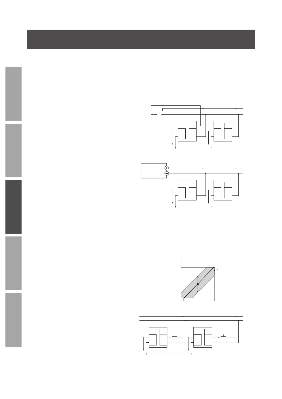
When using a variable resistor
Connect the drivers as shown below.
When using a variable resistor, operate products of 20 units or
less.
Calculation method of resistance (VRx) when the number of
drivers is n
Resistance (VRx) = 20/n (k), n/20 (W)
Example: If two drivers are used
Resistance (VRx) = 20/2 (k), 2/20 (W)
Therefore, the resistance is calculated as 10 k, 1/10 W.
line
riable resistor
VRx
13
2
Driver 1Driver n
VM
VL
L
N
L
N
VH
VM
VL
VH
Power supply
Power
When using external DC voltage
Connect the drivers as shown below.
Calculation method of current capacity (I) of external DC
power supply when the number of drivers is n
Current capacity (I) = 1 × n (mA)
Example: If two drivers are used
Current capacity (I) = 1 × 2 (mA)
Therefore, the current capacity is calculated as 2 mA or more.
DC power
supply
0 to 10 VDC
Speed
line
Driver 1Driver n
VM
VL
L
N
L
N
VH
VM
VL
VH
Power supply
Power
How to adjust the speed dierence
To adjust the speed dierence among the rst motor and the second and subsequent motors, change the parameter or connect
a resistor to adjust.
z
Adjustment by the parameter
The speed dierence can be adjusted by changing the "Analog operation speed command gain" parameter (ID: 1821) and
"Analog operation speed command oset" parameter (ID: 1822) for the second and subsequent drivers. This section explains how
to adjust with the "Analog operation speed command oset" parameter.
Refer to p.60 for how to set the parameter.
•
When the speed of the second motor is slower than that of the rst motor:
Set the oset value to rotate faster (positive side) with the "Analog
operation speed command oset" parameter.
•
When the speed of the second motor is faster than that of the rst motor:
Set the oset value to rotate slower (negative side) with the "Analog
operation speed command oset" parameter.
0
speed
Range of oset
(–2000 to +2000 r/min)
Setting voltage
Positive
direction
Negative
direction
z
Adjustment by a resistor
Connect a resistor of 470
Ω
, 1/20 W to the terminal VM
on the driver 1 and connect a variable resistor VRn of
1k
Ω
, 1/20 W to the driver 2 and subsequent drivers.
470 Ω
1/20 W
VRn
1 kΩ
1/20 W
line
Driver 1Driver n
VM
VL
L
N
L
N
VH
VM
VL
VH
Power
Power
line