Preparation
19
Safety precautions How to use Help Appendix
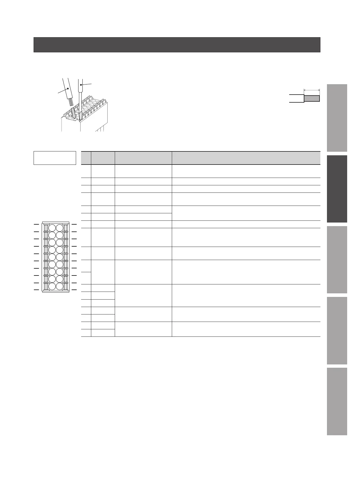
4. Connecting the I/O signals (CN5)
Connect the input signals and output signals to CN5.
Connection method
Applicable lead wire
•
Lead wire size: Stranded wire AWG24 to 18 (0.2 to 0.75 mm
2
)
•
Conductive material: Use only copper wires.
Applicable crimp terminal
Manufacturer: PHOENIX CONTACT GmbH & Co. KG
Model: AI 0,25-10 [Conductor cross-sectional area: 0.14 - 0.34 mm
2
(AWG24)]
AI 0,34-10 [Conductor cross-sectional area: 0.14 - 0.34 mm
2
(AWG22)]
AI 0,5-10 [Conductor cross-sectional area: 0.40 - 0.65 mm
2
(AWG20)]
AI 0,75-10 [Conductor cross-sectional area: 0.65 - 0.82 mm
2
(AWG18)]
Connector model: DFMC1,5/9-ST-3,5
(PHOENIX CONTACT GmbH & Co. KG)
Pin assignment
Pin
No.
Signal
name
Function
*1
Description
1 IN-COM0
Input signals common
(for external power supply)
Connect when using an external power supply.
10
11
12
13
14
15
16
17
18
1
2
3
4
5
6
7
8
9
2 IN0 [FWD] The motor rotates in the forward direction while this signal is being ON.
3 IN1 [REV] The motor rotates in the reverse direction while this signal is being ON.
4 IN2 [STOP-MODE]
Select how to stop the motor. When it is OFF, the motor decelerates to a
stop.
5 IN3 [M0]
Select a desired operation data number by switching the ON-OFF status
of the M0 and M1 inputs.
6 IN4 [M1]
7 IN5 [ALARM-RESET] Reset the alarm presently generated.
8 IN6 [MB-FREE]
*2
Select how the electromagnetic brake would operate (hold/release) when
the motor stops.
If this signal is turned ON, the electromagnetic brake can be released.
9 IN-COM1
0 V
(for internal power supply)
Connect when using the internal power supply.
10
TH TH
When a regeneration resistor is used, connect the thermostat output of
the regeneration resistor (normally closed). If the regeneration resistor
overheats to turn the thermostat output OFF, the “regeneration resistor
overheat” alarm is generated.
11
12 VH
External analog setting
input
Connect when the rotation speed or torque limiting value is set externally
using an external potentiometer or external DC voltage.
(Refer to p.21)
13 VM
14 VL
15 OUT0+
[SPEED-OUT] 30 pulses are output while the motor output shaft makes one revolution.
16 OUT0–
17 OUT1+
[ALARM-OUT] This signal will be output if an alarm is generated. (Normally closed)
18 OUT1–
*1
Signals in brackets [ ] are functions assigned at the time of shipment. For the pin Nos. 2 to 8 and Nos. 15 to 18,
the assigned function can be changed. Refer to p.29 for signals that can be assigned.
*2
Available for only drivers for electromagnetic brake motor
 Loading...