How to use
59
PreparationSafety precautions Help Appendix
Setting method of the rotation speed and torque limiting value
The setting method can be selected using the "Speed, torque limiting command selection" parameter. Refer to the table below
for four types of parameter setting methods.
z
"Speed, torque limiting command selection" parameter (ID: 1820)
Operation
data No.
Setting value: 0 Setting value: 1 Setting value: 2 Setting value: 3
Rotation
speed
Torque
limiting
Rotation
speed
Torque
limiting
Rotation
speed
Torque
limiting
Rotation
speed
Torque
limiting
0
Digital setting Digital setting
Digital setting
Digital setting Analog setting Digital setting Digital setting Analog setting1 Analog setting
2 to 15 Digital setting
Digital setting: Operation panel,
MEXE02
Analog setting: External potentiometer (sold separately), external DC voltage
[Setting value]
•
Digital setting for the rotation speed and torque limiting value in all operation data: "0"
•
Analog setting for one of the rotation speed (operation data No.1), and digital setting for other operation data: "1"
•
Analog setting for the rotation speed, and digital setting for the torque limiting value in each operation data: "2"
•
Digital setting for the rotation speed in each operation data, and analog setting for the torque limiting value: "3"
Calculation method of speed reduction ratio:
"Speed reduction ratio" parameter (ID: 2033), "Speed
reduction ratio digit setting" parameter (ID: 2038)
Set using the "Speed reduction ratio" parameter (ID: 2033) and "Speed reduction ratio digit setting" parameter (ID: 2038).
In the case of motors with the
JH
gearhead, the
JB
gearhead, and the
JV
gearhead, input the actual gear ratio into the gear
ratio of the gearhead. Check the operating manual of the motor for the actual gear ratio.
To display the rotation speed for the gearhead gear ratio
Example)
When the speed reduction ratio 15 is set
Set 150 to the "Speed reduction ratio" parameter and 1 to the "Speed reduction ratio digit setting" parameter.
15 that was calculated by the formula "150 x 0.1" was set.
At this time, one-fteenth speed of the motor rotation speed is displayed.
For example, when the motor rotation speed is 1300, "86.6" is shown on the display.
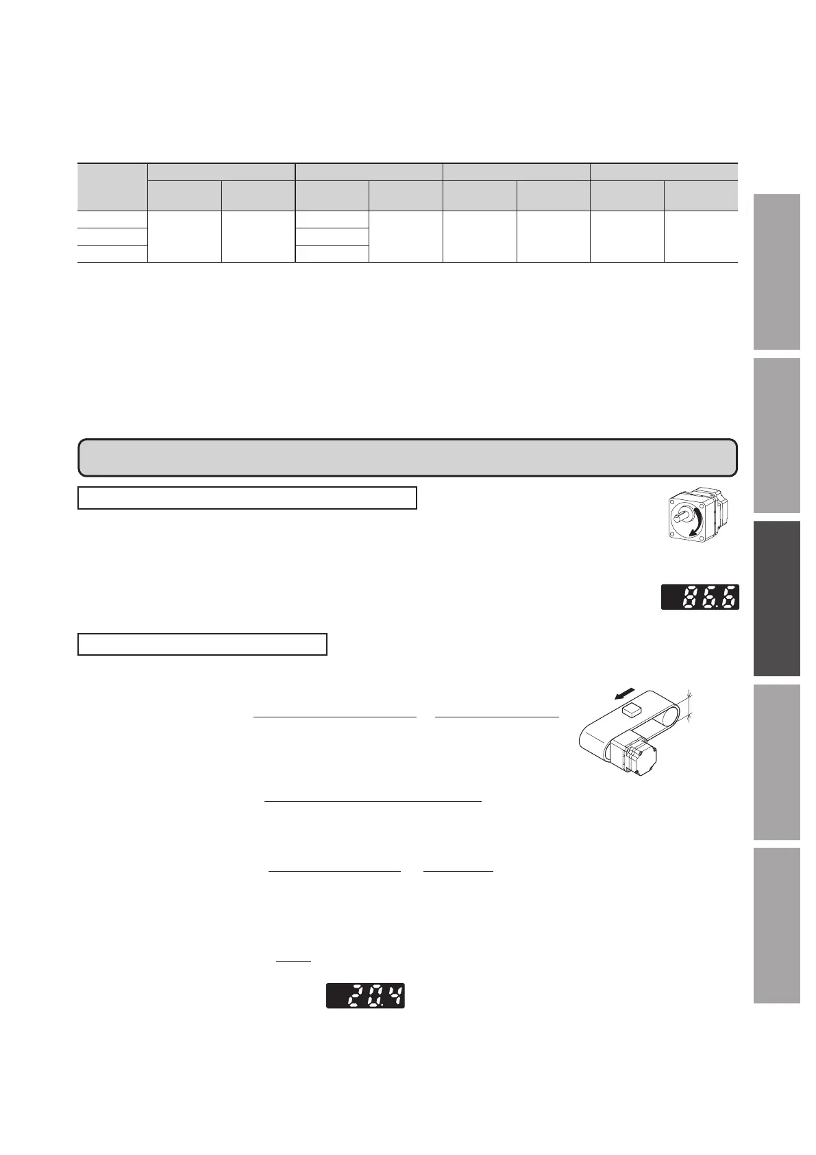
To display as the conveyor transfer speed
To display the conveyor transfer speed, calculate the conveyor speed reduction ratio by using
the formula below and set to the "Speed reduction ratio" parameter.
nveyor speed reduction ratio =
1
Feed rate per motor revolution
Gearhead gear ratio
Pulley diameter [m] × π
=
When the calculated conveyor speed reduction ratio is used, the conveyor transfer speed is
converted as follows.
Pulley
nveyor transfer speed [m/min] =
Motor output shaft rotation speed [r/min]
Conveyor speed reduction ratio
Example)
When the pulley diameter is 0.1 m and the gear ratio of the gearhead is 20
≅
nveyor speed reduction ratio =
Gearhead gear ratio
Pulley diameter [m] × π
=
From the conversion formula, the conveyor speed reduction ratio is calculated as 63.7 in this example.
If the conveyor speed reduction ratio is 63.7 and the rotation speed of the motor is 1300 r/min, the conveyor transfer speed is
converted as follows:
≅
nveyor transfer speed [m/min] =
Accordingly, "20.4" is shown on the display.