Help
73
How to usePreparationSafety precautions Appendix
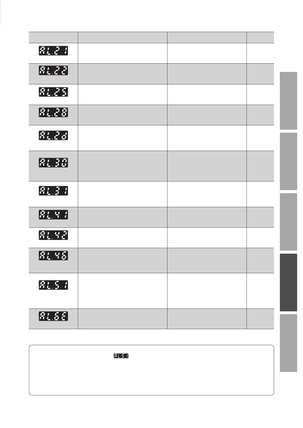
Alarm
Alarm Cause Remedial action
Reset by the
ALARM-RESET
Main circuit overheat
●
The temperature inside the driver exceeded the
detection temperature of the alarm.
●
Reconsider the ambient temperature.
●
Reconsider the ventilation condition in the
enclosure.
Possible
Overvoltage
●
The power supply voltage exceeded
approximately 120% of the rated voltage.
●
A large inertia load was stopped abruptly.
●
Check the power supply voltage.
●
If this alarm is generated during operation,
decrease the load or increase the
acceleration/deceleration time.
Possible
Undervoltage
●
The power supply voltage dropped below
approximately 60% of the rated voltage.
●
Check the power supply voltage.
●
Check the wiring of the power supply
cable.
Possible
Sensor error
●
The sensor line of the connection cable was
disconnected. Or the connection cable was
come o.
●
Check the wiring between the driver and
motor.
Possible
Main circuit output error
*1
●
The power lines of the connection cable were all
disconnected.
Or the connection cable was come o.
●
A dierent combination in output powers for
the motor and the driver was used.
●
Check the wiring between the driver and
motor.
●
Match the output powers for the motor
and the driver.
Possible
Overload
●
A load exceeding the rated torque was applied
to the motor for the time set in the "Overload
alarm detection time" parameter.
The time when the overload alarm is generated
varies according to the load torque.
Refer to p.62 for details.
●
Decrease the load.
●
Reconsider the operating conditions such
as the acceleration/deceleration time.
●
If this alarm is generated in low
temperature environment, perform a trial
operation in a light load state.
Possible
Overspeed
●
The motor detection speed was exceeded 5200
[r/min].
●
A dierent combination in output powers for
the motor and the driver was used.
●
Decrease the load.
●
Reconsider the operating conditions such
as the acceleration/deceleration time.
●
Match the output powers for the motor
and the driver.
Possible
EEPROM error
●
The stored data of the driver was damaged.
●
Initialize the parameters. Not possible
Sensor error at power-on
●
The sensor line of the connection cable was
disconnected before the power is supplied. Or
the connection cable was come o.
●
Check the wiring between the driver and
motor.
Possible
Prevention of operation at
power-on
*2
●
The power supply was turned on again when
the operation input signal was being ON.
●
Before supplying power to the driver, turn
the operation input signal OFF.
Possible
Regeneration resistor
overheat
●
The regeneration resistor is not connected
properly.
●
The regeneration resistor was overheated
extraordinarily.
●
Check the connection for the thermostat
output and the TH input of the
regeneration resistor.
●
The power consumption of the
regeneration resistor exceeds the
allowable level. Reconsider the load
condition and operating condition.
Possible
External stop
●
The EXT-ERROR input was turned OFF.
●
Check the EXT-ERROR input. Possible
*1
This alarm is not generated when the torque limit value is set to approximately 60% or less.
*2
This alarm can be disabled with the "Prevention of operation at power-on alarm" parameter. Refer to p.62 for details.
About regeneration resistor overheat alarm
The regeneration resistor overheat alarm “ ” may be generated even if the regeneration resistor is not connected.
Once the main power supply is turned on in a state where the pin Nos. 10 and 11 (TH input) of CN5 are short-circuited, the
driver recognizes that the regeneration resistor is connected and changes to the setting that the regeneration resistor is
used. After that, if the power supply is turned on again in a state where nothing is connected to the pin Nos. 10 and 11 of
CN5, the regeneration resistor overheat alarm will be generated.
To cancel the setting to use the regeneration resistor, execute initialization of parameters without connecting anything to
the pin Nos. 10 and 11 of CN5. Then, turning on the main power supply again will reset the alarm.