Help
75
How to usePreparationSafety precautions Appendix
Information
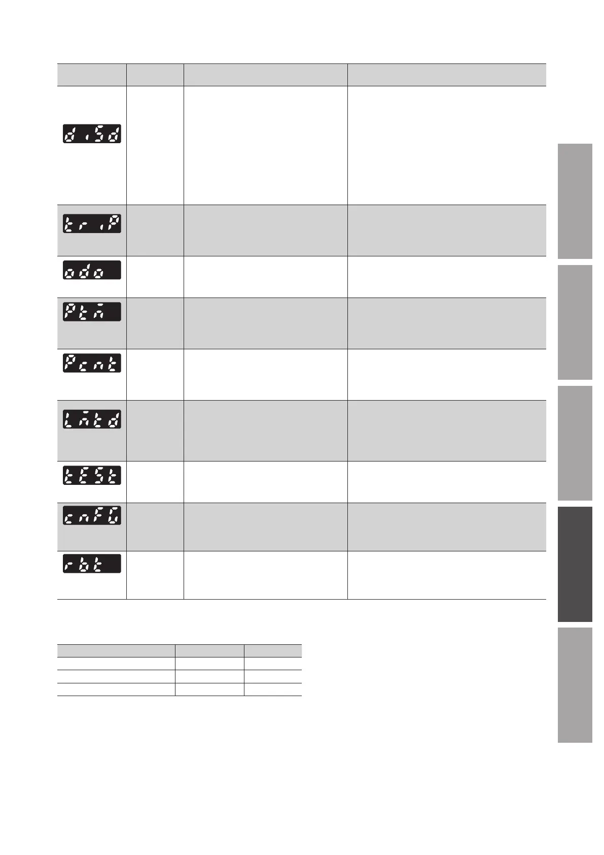
Information bit
output signal
Cause Condition to reset and clear
Operation
prohibited
*1
INFO-DRV
●
The operation input signal is being ON when
the test mode has switched to other mode.
●
The operation input signal is being ON
when I/O test of the
MEXE02
or teaching/
remote operation has completed.
●
Conguration was executed in a state where
the motor would immediately rotate when
the assignment or the logic level setting of
input terminals was changed.
●
The operation input signal is being ON when
the local control operation has switched to
the remote control operation.
●
The operation input signal was turned OFF.
Tripmeter
INFO-TRIP
●
The rotation amount inside the driver
increased to the setting value or more of the
"Tripmeter information" parameter.
The following operation was performed, and the rotation
amount inside the driver fell below the setting value of
the "Tripmeter information" parameter.
●
The "Tripmeter information" parameter was set again.
●
Tripmeter was cleared using the
MEXE02
.
Odometer
INFO-ODO
●
The integrated rotation amount inside the
driver increased to the setting value or more
of the "Odometer information" parameter.
The following operation was performed, and the rotation
amount inside the driver fell below the setting value of
the "Odometer information" parameter.
●
The "Odometer information" parameter was set again.
Main power
supply time
INFO-PTIME
●
A time period having supplied the power
to the main power supply of the driver
increased to the setting value or more of
the "Main power supply time information"
parameter.
●
The "Main power supply time information" parameter
was set again, and the time period having supplied
the power to the main power supply of the driver fell
below the setting value of the "Main power supply
time information" parameter.
Main power
supply count
INFO-PCOUNT
●
The number of times for turning on the
main power supply of the driver increased
to the setting value or more of the "Main
power supply count information" parameter.
●
The "Main power supply count information" parameter
was set again, and the number of times for turning
on the main power supply of the driver fell below
the setting value of the "Main power supply count
information" parameter.
Start operation
restricted mode
INFO-DSLMTD
●
The local control operation is performed.
*2
●
Conguration was executed.
●
"Teaching/remote operation" was executed
using the
MEXE02
.
●
Writing was performed using the
MEXE02
.
●
Initialization was executed.
●
The local control operation was complete.
●
Remote control operation was performed.
●
Conguration was complete.
●
"Teaching/remote operation" was released.
●
Initialization was complete.
I/O test mode
INFO-IOTEST
●
“I/O test” was executed using the
MEXE02
.
●
Conguration was executed.
●
The screen was moved to the "test mode”
using the operation panel.
●
I/O test was released.
●
Conguration was complete.
●
The screen on the operation panel changed to other
than the "test mode."
Conguration
request
INFO-CFG
●
The parameter change required
conguration was executed.
●
Conguration was executed.
Power cycling
request
INFO-RBT
●
The parameter change required to cycle the
driver power was executed.
●
The driver power was turned o, and turned on again.
*1
The motor does not rotate while the operation prohibited information is generated.
*2
The ALARM LED does not blink when the local control operation is performed.
z
Setting value of related parameters
Parameter name Setting range Factory setting
Overvoltage information 280 to 440 [VDC] 435
Undervoltage information 120 to 280 [VDC] 120
Load information 10 to 300 [%] 300
Details of parameters
⇒
p.61
•
The setting values for the overvoltage information and the undervoltage information represent the value of the main circuit DC
voltage inside the driver.
The main circuit DC voltage is approximately equal to the power input voltage multiplied by the square root of 2.
In the case of single-phase 100-120 VAC types, however, the value is approximately equal to double the power input voltage
multiplied by the square root of 2.
[Example] When the input voltage is 100 VAC, the main circuit DC voltage inside the driver is approximately 283 VDC.
When the input voltage is 240 VAC, the main circuit DC voltage inside the driver is approximately 340 VDC.