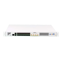
# Name Information Ref.
#1 Power button Power On/Off the device
#2 Reset Button Button used to perform a factory
reset or enter the recovery/failsafe
mode
"Recovery Mode" on page130
#3 Status LED Green, Orange, Red
"System Status" on page10
#4 1x Management
UART (RJ45)
Serial UART RS232 on a RJ45 con-
nector with pinout
(USB-RJ45/RS232 adaptor not
included)
"Logging from the UART" on
page20
Pin #1:
✖
Pin #2:
✖
Pin #3
RXD
Pin #4
GND
Pin #5:
✖
Pin #6:
TXD
Pin #7:
✖
Pin #8:
✖
#5 2x Man-
agement Eth-
ernet (RJ45)
10/100/1000 ethernet network inter-
face (eth0 & eth1)
"Product Specifications" on
page13
#6 16x SFP Fiber
ports
1Gbps SFP compatible
"White Rabbit" on page58"IEEE
1588-2008 (PTPv2)" on
page62
Timing input
#7 Timing Input
LED
OK: Green; Warning: Yellow; Critical:
Red
"Timing Output" on page11
#8 10 MHz input
● SMA connector (F)
● 50 Ω termination
● 1Veff (+/-30%) digital or sine
wave
"External Reference (GM)" on
page73
 Loading...