4 SETUP INSTRUCTIONS
inc All rights reserved
53
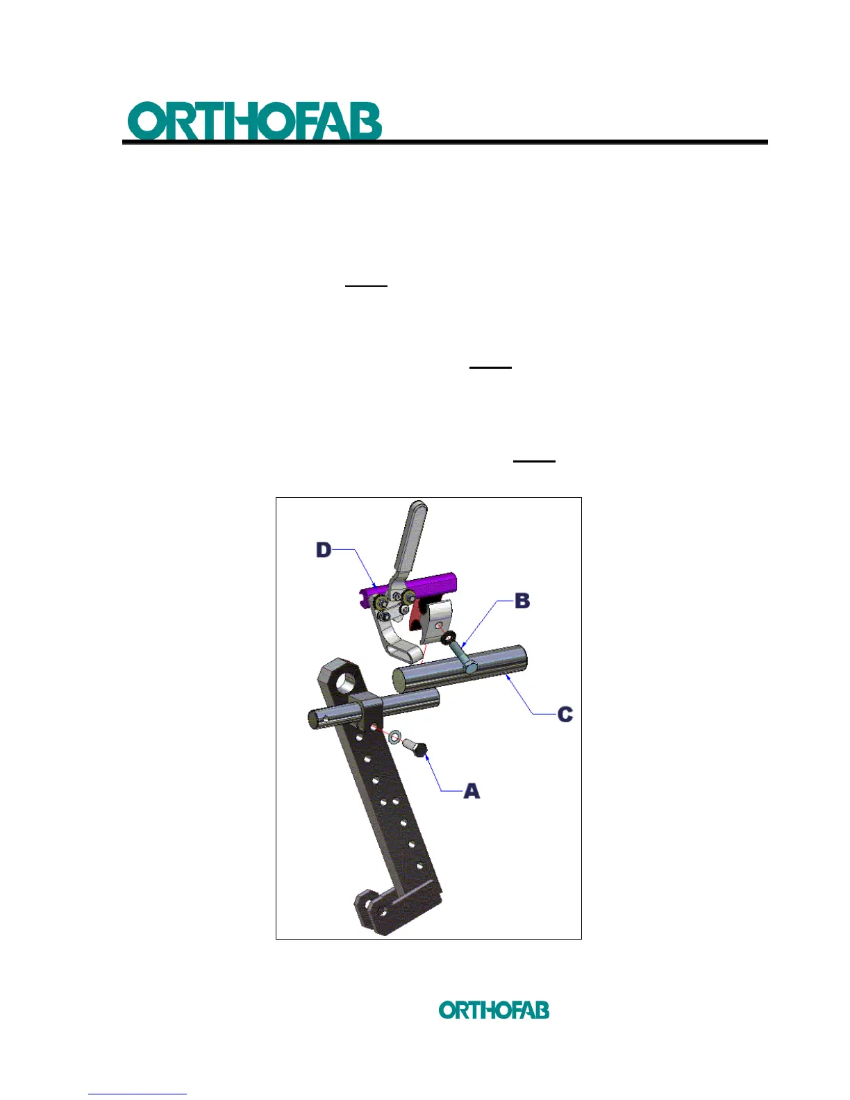
b) Adjustment according to the position of the rear 20, 22 or 24 inches wheels :
When the position of the rear wheels has been determined (section 4.9.2), the
brake support should be repositioned (see; figure 31-A).
1. Loosen the (A) screw, using a 1/2" key. The (C) support can now slide in the
tightening mechanism. NOTE
: The biggest shaft on the (C) support must be
placed upward as shown at figure 31-A ;
2. Loosen slightly the (B) screw, using a 13 mm key, this will allow the parking brake
tightening bracket, to slide on the biggest shaft of the (C) support and the parking
brake (D) to slide in the tightening bracket. NOTE: The parking brake (D) support
must be inverted as shown at figure 31-A ;
3. Tighten the entire assembly and make sure that when engaging the brake the
movement is carried out without effort ;
4. Finish this adjustment as per section 4.10.1 a). NOTE: (A) screw on figure 30
section 4.10.1 a) is the same as (A) screw on the figure 31-A below.
Figure 31-A : Installation of the parking brake on its support (standard propulsion).