29
Bench Alignment Process
+ = anterior placement / – = posterior placement (in relation to the alignment reference line)
No. Reference measurements and positions for bench alignment, assembly tasks
External rotation of the prosthetic knee joint:
approx.5°
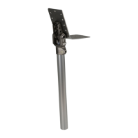
Join the prosthetic foot and the prosthetic knee joint with the chosen adapters (e.g.
torsion adapter, tube adapter, tube clamp adapter).
Observe the adapter instructions for use during adaptation and installation.
Orientation of the two prosthetic joints:
joint axes parallel to each other
Orientation of hip prosthesis socket with lamination plate and prosthetic hip joint:
lamination plate positioned horizontally
hip prosthesis socket as far in anterior direction as possible on the lamination plate
TMS line on the hip prosthesis socket parallel to the alignment reference line at a dis
tance of 20mm anterior
orientation of the hip prosthesis socket according to the dorsal pelvis inclination mark
ing
orientation of the centre front of the lamination plate according to the frontal reference
line
pelvis rotation line 90° to the walking direction
INFORMATION
The 647H540 Quick Start Guide includes selection tables for easier selection of the
tube clamp adapters.
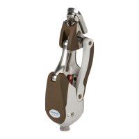
Join the prosthetic hip joint and the prosthetic knee joint using the chosen adapters
(e.g. rotation adapter, tube clamp adapter, tube).
Observe the adapter instructions for use during adaptation and installation.
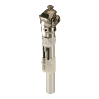
Changing the length of the tube above the prosthetic knee joint changes the distance between
the partial mass centre of gravity line and the alignment reference line. This distance sub
sequently has to be reset to the nominal value of 20mm.
5.5 Static Alignment
Alignment Recommendations
(Schematic of static alignment for 3R60=HD see fig.19 – the 647H540 Quick Start Guide con
tains all schematics for static alignment with the 3R60, 3R106=HD and 3C98-2 C-Leg.)
If the prosthesis is fabricated with the 3B1 Genium prosthetic knee joint, the static alignment
instructions in conjunction with the 7E10* prosthetic hip joint from the seminar documentation and
the instructions for use for the prosthetic knee joint as well as X-Soft apply. Compliance with the
specifications in the following alignment recommendations is also required.
Static Alignment Process
+ = anterior placement / – = posterior placement (in relation to the load line)
No. Reference measurements and positions for static alignment, adjustment tasks
Required materials and tools:
743L100 L.A.S.A.R. Posture
Set the prosthetic hip joint to the factory defaults (see the chapter "Dynamic Trial Fit
ting" – see Page30).
Tighten the screws to the specified torque values (see the chapter "Finishing the
Prosthesis" – see Page34).
Verify the length of the prosthesis on the patient.
 Loading...