30
Static Alignment Process
+ = anterior placement / – = posterior placement (in relation to the load line)
No. Reference measurements and positions for static alignment, adjustment tasks
To determine the load line, position the patient on the L.A.S.A.R. Posture as follows:
• Prosthetic foot (with shoe) on force plate (sufficient load: >35% body weight)
• Other foot (with shoe) on height compensation plate
• The tips of the shoes are in one line
• The load line should run approx.50mm (±10mm) anterior to the ankle adapter
screw (depending on the type and size of the prosthetic foot) as well as approx.0
to±10mm through the TMS line.
Optimise the static alignment solely by changing the plantar flexion on the foot
adapter.
a–p positioning of the alignment reference point (rotation axis of the prosthetic knee
joint) to the load line:
3R60=HD (anterior, lower axis): -10mm
3R106=HD (anterior, upper axis): -35mm
3C98-2: -30mm
5.6 Dynamic Trial Fitting
INFORMATION
►
Please make sure you are thoroughly familiar with the adjustment possibilities and their
effects! Only then you will be able to optimally adjust the prosthesis to the requirements of
the prosthesis wearer.
5.6.1 Adjustments
INFORMATION
Secure the prosthetic hip joint on the lamination plate solely with the accessories which are
included in the scope of delivery!
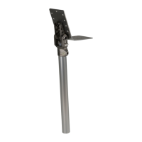
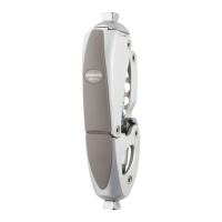
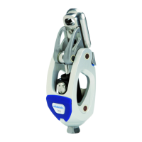
1) Abduction/adduction (see fig.14): To adjust, loosen the lower and upper screws and turn
the joint around the lower screw. Then tighten the screws again. For the required torque val
ues and tools, see the table in the chapter "Finishing the Prosthesis" see Page34.
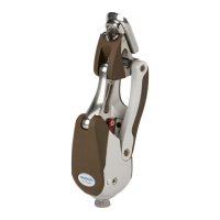
2) Rotation (see fig.15): Mark abduction/adduction with a pen. To adjust internal (medial) and
external (lateral) rotation, loosen the lower, middle and upper screws. Then tighten the screws
again. For the required torque values and tools, see the table in the chapter "Finishing the
Prosthesis" see Page34.
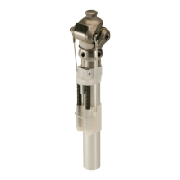
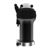
3) Distal adjustment of the prosthetic hip joint (see fig.16, see fig.17): The lower pyramid
adapter permits tilting of the prosthetic hip joint in ML and AP directions. This is done for cor
rect alignment of the prosthetic hip joint in the prosthesis.
5.6.2 Adjustment Possibilities
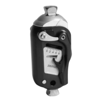
Swing phase damping (SW)
(see fig.20)
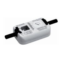
Stance phase damping (ST)
(see fig.21)
Parameter The free swing phase is fol
lowed by a significant increase
in damping to limit the stride.
The extension movement can
be damped in the stance
phase, allowing comfortable
extension of the prosthesis.
 Loading...