Oxford Technical Solutions Ltd Page 7 of 110
List of figures
Figure 1: Windows Firewall warning message ............................................................................................................................. 22
Figure 2: RT3000 v4 mounting points (mm) ................................................................................................................................ 23
Figure 3: Dual antenna orientations ................................................................................................................................................ 25
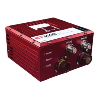
Figure 4: RT3000 v4 front panel layout .......................................................................................................................................... 26
Figure 5: RT3000 v4 I/O connector pin layout ............................................................................................................................. 28
Figure 6: RT3000 v4 main user cable ............................................................................................................................................. 31
Figure 7: RT3000 v4 auxiliary user cable ....................................................................................................................................... 33
Figure 8: 1PPS waveform ..................................................................................................................................................................... 34
Figure 9: RT3000 v4 IMU coordinate frame axes ....................................................................................................................... 36
Figure 10. IMU measurement origin ................................................................................................................................................ 37
Figure 11: OxTS NED navigation frame definition ....................................................................................................................... 38
Figure 12: ISO 8855 ENU earth-fixed system .............................................................................................................................. 39
Figure 13: OxTS horizontal frame definition ................................................................................................................................. 40
Figure 14: ISO 8855 intermediate system ..................................................................................................................................... 40
Figure 15: Vehicle frame definition .................................................................................................................................................. 41
Figure 16: ISO 8855 vehicle system ................................................................................................................................................. 42
Figure 17: Configuring the computer’s IP address for Ethernet data transmission ..................................................... 43
Figure 18: In-line RJ-45 coupler ....................................................................................................................................................... 44
Figure 19: NAVconfig Home section ................................................................................................................................................ 48
Figure 20: NAVconfig Start/Read Configuration section ......................................................................................................... 49
Figure 21: NAVconfig Read Configuration section ..................................................................................................................... 50
Figure 22: An RT device mounted on our RT-Strut .................................................................................................................... 51
Figure 23: NAVconfig IMU orientation tab in the Hardware Setup section ....................................................................... 52
Figure 24: NAVconfig Primary Antenna tab ................................................................................................................................... 53
Figure 25: NAVconfig Secondary Antenna tab in the Hardware Setup section ............................................................... 54
Figure 26: NAVconfig Lateral No-slip tab in the Hardware setup section ......................................................................... 55
Figure 27: Measurement point for Lateral No-slip ..................................................................................................................... 56
Figure 28: NAVconfig Lateral No-slip tab in the hardware Setup section ......................................................................... 57
Figure 29: NAVconfig Differential corrections tab in the Hardware Setup section ....................................................... 58
Figure 30: NTRIP internal client ......................................................................................................................................................... 59
Figure 31: NAVconfig CAN output configuration tab ................................................................................................................. 63
Figure 32: NAVconfig CAN output configuration tab - Navigation ....................................................................................... 64
Figure 33: CAN-FD output configuration ....................................................................................................................................... 66
Figure 34: CAN-Acquisition tab .......................................................................................................................................................... 67
Figure 35: NAVconfig surface tilt properties in the environment section within NAVconfig ..................................... 71
Figure 36: NAVconfig enable local co-ordinates in the environment section ................................................................. 72
Figure 37: NAVconfig acceleration filters tab in the advanced tools section .................................................................. 73
Figure 38: NAVconfig wheel speed Input tab in the advanced tools section ................................................................... 75
Figure 39: NAVconfig output smoothing properties window ................................................................................................. 76
Figure 40: NAVconfig Slip Points tab ............................................................................................................................................... 78
Figure 41: NAVconfig GNSS Control tab in Advanced Tools within NAVconfig ................................................................. 79
Figure 42: NAVconfig Global Coordinate System properties window ................................................................................. 81
Figure 43: NAVconfig Write Configuration page .......................................................................................................................... 83
Figure 44: NAVconfig home section ................................................................................................................................................. 86
Figure 45: NAVconfig read configuration ....................................................................................................................................... 87