Optional Controller
Manual of Controller
2 - 31
2. Wireless Remote Controller
( CZ-RWSU2N, CZ-RWSD2, CZ-RWST3N, CZ-RWSL2N )
2. Names and Operations
8
(EN)
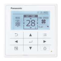
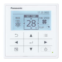
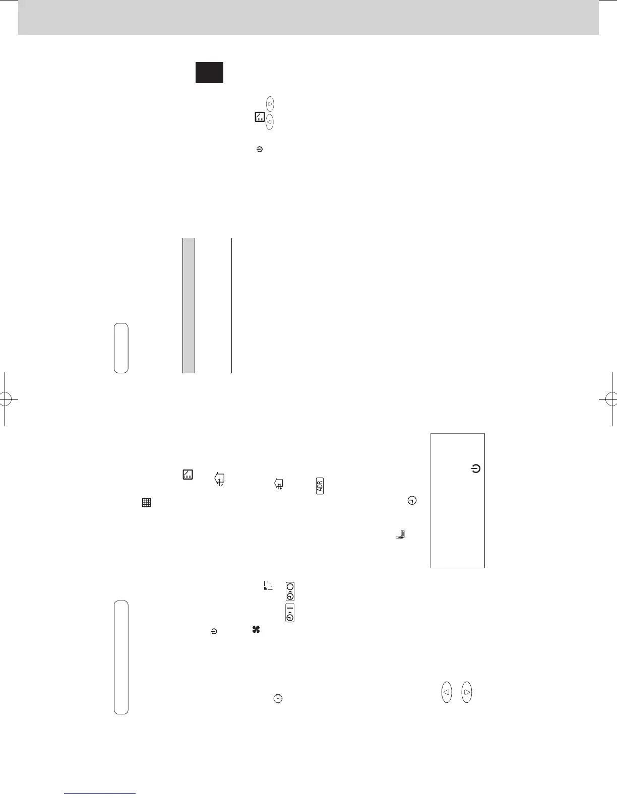
REMOTE CONTROLLER
One remote controller can control a group of
up to eight indoor units. (See page 17)
1. Operation Display
Displays the operation status.
(The gure shows all the
statuses.)
• The auto- ap display may be
different, depending on the
installed unit. (See page 16.)
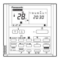
2. Start/Stop button
Pressing this button once starts
and pressing again stops the
operation.
3. Fan speed button
4. Swing/Wind Direction button
5. Timer setting button
Use for operating with a timer.
6. Reset button
Use this button after changing the
batteries.
7. Cover
Press at the top center and then
slide down.
8. Transmitter
9. Remote control sensor
Detects the temperature at the
remote controller when detection
has been switched to the remote
controller by the sensor button.
10. Temperature setting buttons
raises the temperature
setting 1 °C at a time.
lowers the temperature
setting 1 °C at a time.
11. Filter button
CZ-RWSC3
Press to turn off the lter lamp on
the receiver.
12. Mode Select button
Press to switch the operation
mode.
13. Ventilation button
Use this when connected to an
aftermarket fan. Pressing this
button starts and stops the fan.
When the air conditioner is started
or stopped, the fan starts or stops
at the same time. (
appears on
the display of the remote
controller when the fan is
operating.)
14. Address button
15. Sensor button
Used this to activate the
temperature sensor on the remote
controller instead of the one on
the indoor unit. The temperature
sensor on the indoor unit is
selected before shipment. At this
time
is shown on the display.
16. Clock button
Use this to set the clock.
From this page, the names of
remote controller’s buttons will be
indicated with the above
illustrations.
E.g.: Start/Stop button
00OI303000.indb8 2015/02/2016:23:01
ENGLISH
9
(EN)
1. Receiver
Receives the signal sent from the
remote controller.
2. Emergency operation button
Indicator lamps
When an error occurs, one of the lamps
ashes. When an indicator lamp is
ashing, refer to “14. Before Requesting
Service”.
3. OPERATION lamp
Lights up when the unit is
operating.
4. TIMER lamp
Lights up when the timer is set.
5. STANDBY lamp
• The lamp in the HEAT mode
lights up at the following times:
during the startup, during the
thermostat operation, and during
the defrosting.
• The lamp ashes when an error
occurs.
6. FILTER lamp
This lamp is for notifying you
when the lter needs to be
cleaned.
7. Address switch
See “11. Addresses”.
Note
• If non-cooling/heating free type is
being used, it will beep twice and the
operating lamp will light up on the
display; if the timer and standby lamps
blink alternately, a con ict between the
heating and cooling exists, so the unit
cannot operate in the desired mode.
(On models that do not have an Auto
function, even if Auto is selected, it
works in the same way.)
• When the local operation is disabled
by centralized control or similar cause,
and if the Start/Stop
, Mode or
Temperature setting button
is pressed, the unit will beep ve times
and the change will not be made.
2. Names and Operations (Cont.)
Receiver
00OI303000.indb9 2015/02/2016:23:02
SM830241-00_2WAY SYS.indb 31 2015/03/26 14:55:09
 Loading...