Optional Controller
Manual of Controller
Optional Controller
Manual of Controller
2 - 45
2. Wireless Remote Controller
( CZ-RWSU2N, CZ-RWSD2, CZ-RWST3N, CZ-RWSL2N )
13
Common to All Models
ENGLISH
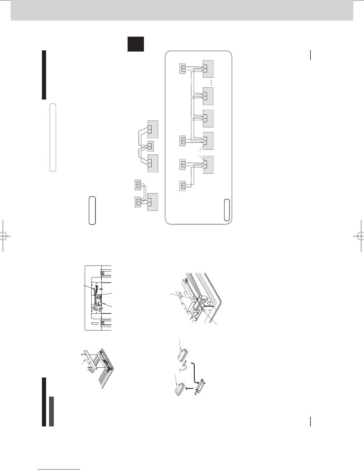
5-1. Wiring for the Receiver
Installation Location for the Reciver
The wireless remote controllers use a very weak infrared light for its signal, which can result in the signal
not being received because of the following inuences, so take care in where the unit is installed.
•
Inverter or rapid-start type uorescent lights (Models without glow lamps)
•
Plasma display or LCD televisions
•
Direct sunlight or other sources of bright light
Attention
Multiple wireless remote controllers cannot be used simultaneously for a single indoor unit.
Be careful not to connect cables to other terminals of indoor units (e.g. power source wiring terminal).
Malfunction may occur.
Do not bundle together with the power source wiring or store in the same metal tube. Operation error may
occur.
If noise is induced to the unit power supply, attach a noise lter.
Installation when setting Main/Sub for the remote controller and the receiver
After installation, according to the “Settings” section, set one to [Main] and the other to [Sub].
Setting the wired remote controller to [Main] is recommended.
The remote controller and the receiver can be connected to any indoor unit for operation.
Note
12 12
R1 R2R1 R2R1 R2R1 R2
RC wiring (eld supply)
• No polarity
Indoor unit Indoor unit Indoor unit Indoor unit
1212
R1 R2
Terminals for
RC wiring
Receiver (Sub) Receiver (Sub)
Wired RC (Main)
Wired RC (Main)
Indoor unit
Using 1 indoor unit
Using more than 1 indoor unit
RC wiring
(eld supply)
• No polarity
Installation
example
R1 R2
R1 R2 R1 R2
12 12
12
Wired RC Receiver
Indoor unit Indoor unit Indoor unit
RC wiring
Receiver
*Wiring shown below is prohibited.
270059_all.indb 13 2015-1-20 9:53:48
12
CZ-RWSL2N
Metal Panel
Installing the Operation Panel
1 Remove the 2 screws and remove the cover A from the back of the panel. (Fig. A)
2
Fasten the operation panel to the location shown in the gure below with the 2 supplied screws (4 × 10). (Fig. B)
3 Pass the receiver wiring (6P white connector) through the back of the panel.
Installing the Receiver
1 The
cover B is t in the Cover A. Spread the points as indicated in gure C and remove it.
The tape holding cover B is only to protect it during transport. Remove and discard it.
2 Connect the receiver wiring (6P white connector) that is sticking out from the operation
panel to the receiver and t the receiver into the panel.
Make sure the 6P white connector is fully plugged in all the way.
3 Pass the lead wire for the receiver through the cutout in the panel and the hole in the
metal panel. Then fasten it to the hole in the metal panel with the plastic clamper. (Fig. D)
4 Attach the cover A.
5 Properly route the lead wire of the operation panel and fasten it with the twist lock. (Fig. B)
6 Install the ceiling panel.
For more information about wiring and test runs, see the sections on “Wiring for the Receiver” and
“Test Operation”.
Fig. A Cover A Fig. B
Loop extra wiring and fasten with
a twist lock.
Operation panel
Supplied screws (4 × 10)
Fig. C Cover B
Connect
Spread
Receiver
Fasten the lead wire to hole in metal panel
Pass through cutout
Fig. D
270059_all.indb 12 2015-1-20 9:53:47
SM830241-00_2WAY SYS.indb 45 2015/03/26 14:55:21
 Loading...