Optional Controller
Manual of Controller
2 - 41
2. Wireless Remote Controller
( CZ-RWSU2N, CZ-RWSD2, CZ-RWST3N, CZ-RWSL2N )
5
CZ-RWSU2N
ENGLISH
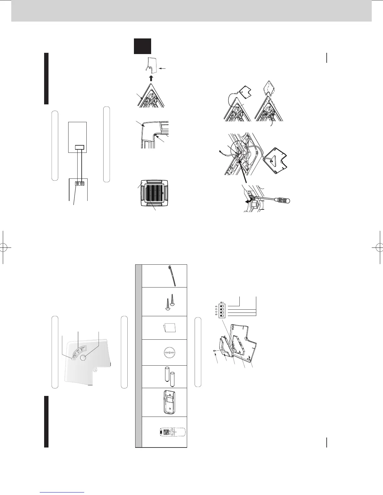
1-5. Installing the Receiver
The receiver can only be installed on the corner indicated in Fig. A. Consider how the panel will
face when it is installed on the indoor unit.
1 Remove the air inlet grill.
2
Remove the screw holding the adjustable corner cover. Then slide the cover to the side and remove it. (Fig. B)
Fig. A Fig. B
3 To pass the wire through the panel, bend the part (shaded area) on the square hole and then
pass wire protruding from the wireless receiver through the grill. (Fig. C)
4
After wiring according to the directions in “Wiring for the Receiver” below, leave enough wire length so
that the receiver’s adjustable corner cover can be removed and fasten the wire with the clamper. (Fig. C)
5
Hang the corner cover string on the pin of the ceiling panel (Fig. D). Then slide the corner cover
onto the ceiling panel until the three clips are correctly located and x it in place with the screws.
Make sure the wire is not caught.
Refer to the installation instructions supplied with the panel
.
For more information about wiring and test operation, see the sections on “Wiring for the Receiver” and
“Test Operation”.
Box with
indoor unit’s
electrical
parts
Bend the part (shaded
area) with a screwdriver
or similar implement to
allow the wire to pass
through.
Fix it in place
with the
clamper.
Pin
Fix the
screw.
Make sure the three clips on the corner
cover are located over the holes on the
ceiling panel and x it in place with the
supplied screws.
Receiver position
Adjustable corner cover
Ceiling panel
Adjustable corner cover
Fig. C
Screw
Fig. D
1-4. Wiring for the Receiver
Wiring Diagram
How to Connect the Wires
・
Connect the wires from the receiver to the terminals for RC wiring on the indoor unit.
(No polarity)
CN001
1
2
Receiver PCBIndoor unit
Terminals for RC
wiring
2P white
270059_all.indb 5 2015-1-20 9:53:36
4
CZ-RWSU2N
1-1. Part Names
1-2. Supplied accessories
1-3. Settings
(2) Emergency operation button
Starts/Stops emergency operation.
(3) Indication lamp
Indicates operation status.
(1) Light receiving section
Receives signals.
Screw
Clamper
PCB
cover
Receiver
PCB
Main/Sub selector
switch for remote
controllers (4)
OFF: Main
ON: Sub
Set its address
(1) to (3)
Corner
cover
All set at OFF
when shipped
from the factory.
ON
123 4
Before installing the receiver,
see the sections on “Wiring for the
Receiver” and “Setting Address
Switches”.
Then check the settings
of the [S003] DIP switch
on the receiver’s PCB.
* Remove the cover from the
receiver when performing the
PCB settings.
Supplied accessories
Wireless Remote
Controller
(1)
Remote Control
Holder
(1)
LR03 Size
Battery
(2)
Operating
Instructions
(1)
Quick
Reference
(1)
Wood Screw
M4 × 16
(2)
Clamper
(1)
270059_all.indb 4 2015-1-20 9:53:35
SM830241-00_2WAY SYS.indb 41 2015/03/26 14:55:16
 Loading...