1 - 4
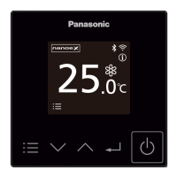
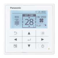
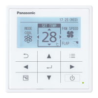
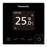
Optional Controller
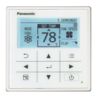
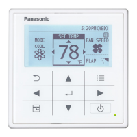
Remote Controller Functions
1
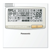
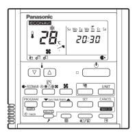
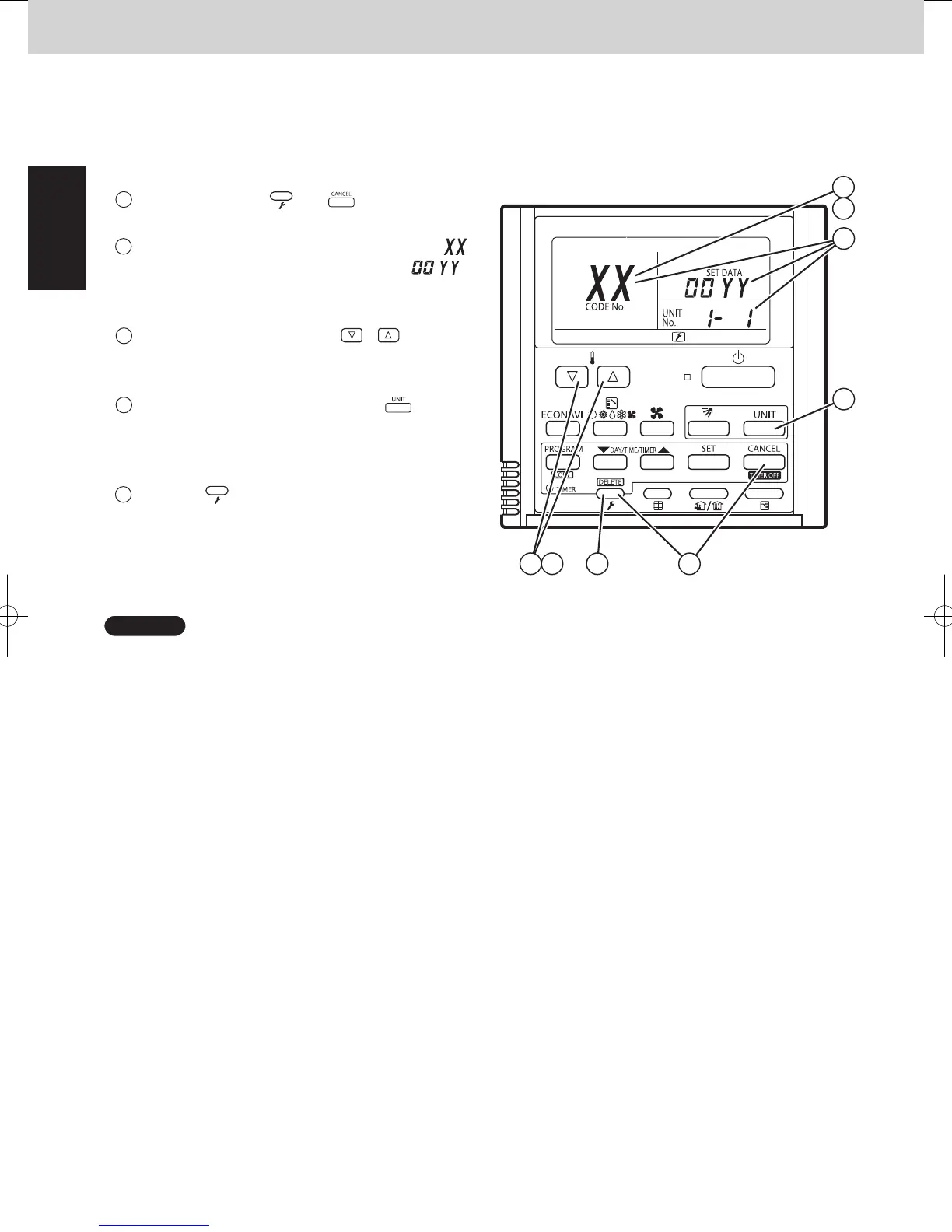
3. Sensor Temperature Display
1
Press and hold the and buttons
simultaneously for 4 seconds or longer.
2
The unit No. “X-X” (main unit No.), item code “ ”
(sensor address), and servicing monitor “
”
(sensor temperature) are displayed on the remote
controller LCD display. (See Fig. 3 at right.)
3
Press the temperature setting /
and select the item code to the address of the
buttons
sensor to monitor.
4
If group control is in effect, press the
to select the unit to monitor.
button
Press the temperature setting buttons to select the
item code to change.
5
Press the button to return to normal remote
controller display.
Fig. 3
A
°
°
4
3
4
3 4 5
1
2
Sensor Temperature Display Function
(displayed regardless of whether unit is operating or stopped)
The procedure below displays the sensor temperatures from the remote controller, indoor unit, and outdoor unit on
the remote controller.
NOTE
The temperature display appears as “- - - -” for units that are not connected.
* If monitor mode is engaged while normal operation is in progress, only the parts of the LCD display shown in the
figure will change. Other parts continue to display the same information as during normal operation.
2WAY SYSTEM
Remote Controller Functions
3. Remote Controller Servicing Functions
Indoor unit sensors
Remote controller temp.
Indoor unit intake temp. (TA)
Indoor unit heat exchanger
temp. E1 (E1)
—
Indoor unit heat exchanger
temp. E3 (E3)
Discharge air temp. (BL)
Discharge air temp. setting
01
Room temp. controlled*00
02
03
04
05
06
07
08
*Room temp. controlled: = Controlled room temperature
•When body thermostat controlled:
Controlled room temperature = Indoor unit intake temp. (TA) – Intake temperature shift (*1)
•Remote control thermostat controlled:
Controlled room temperature = Remote controller temp.
*1 Intake temperature shift: This is the shift value considered the temperature difference between the upper area
and lower area of the room in heating mode.
It is the value of the code “06” in the indoor unit’s EEPROM setting.
Cooling mode: = 0
Indoor unit MOV pulse (MOV)
Outdoor unit sensors
Unit No.1 Unit No.2 Unit No.3
Discharge temp. 1 (DISCH1)
Discharge temp. 2 (DISCH2)
Discharge temp. 3 (DISCH3)
High-pressure sensor temp.
Heat exchanger gas 1 (EXG1)
Heat exchanger liquid 1 (EXL1)
Heat exchanger gas 2 (EXG2)
Heat exchanger liquid 2 (EXL2)
Outdoor air temp. (TO)
—
Inverter primary current 1
CT2
CT3
MOV pulse 1 (MOV1)
MOV pulse 2 (MOV2)
Actual operating frequency
MOV pulse 4 (MOV4)
—
—
Low-pressure sensor temp.
Suction temp. (SCT)
Detected oil temp. 1 (OIL1)
Detected oil temp. 2 (OIL2)
Detected oil temp. 3 (OIL3)
—
—
0A
0B
0C
0D
0E
0F
10
11
12
13
14
15
16
17
18
19
1A
1B
1C
1D
1E
1F
20
21
22
23
24
2A
2B
2C
2D
2E
2F
30
31
32
33
34
35
36
37
38
39
3A
3B
3C
3D
3E
3F
40
41
42
43
44
4A
4B
4C
4D
4E
4F
50
51
52
53
54
55
56
57
58
59
5A
5B
5C
5D
5E
5F
60
61
62
63
64
Temp. sensor at refrigerant gas
outlet of dual-tube temp. (SCG)
ex.) 2WAY VRF SYSTEM
SM830241-00_2WAY SYS.indb 4 15/04/07 10:00:29
 Loading...