Optional Controller
Manual of Controller
2 - 44
2. Wireless Remote Controller
( CZ-RWSU2N, CZ-RWSD2, CZ-RWST3N, CZ-RWSL2N )
11
CZ-RWSL2N
ENGLISH
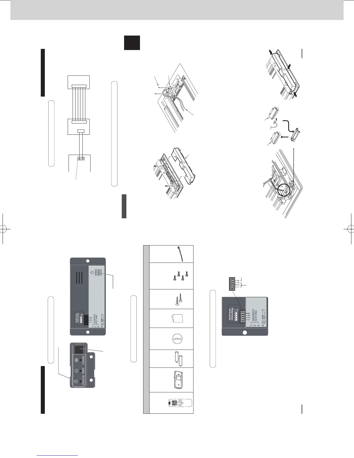
4-5. Installing the Receiver/Operation Panel
Resin Panel
Installing the Operation Panel
1 Remove the 2 screws. Then remove the cover A from the back of the panel. (Fig. A)
2 Fasten the operation panel to the location shown in the gure below with the 2 supplied screws
(4 × 10). (Fig. B)
3 Pass the receiver wiring (6P white connector) through the back of the panel.
Installing the Receiver
1 The cover B is tted in the cover A. Remove the 1 screw and detach it by pressing from the front
side of the panel. (Fig. C)
2 Connect the receiver wiring (6P white connector) that is sticking out from the operation panel to
the receiver and t the receiver into the panel.
Make sure the 6P white connector is fully plugged in all the way.
3 Bend the lead wire of the receiver into shape so that it does not come in contact with the louver
shaft.
There is a groove to pass the wire (circled part in Fig. C). Insert the lead wire into this groove
with no slack.
4 Attach the cover A until it is rmly engaged in the claws indicated by arrows. (Fig. D)
5 Arrange the lead wire of the operation panel appropriately and fasten it with the supplied
clamper.
6 Install the ceiling panel.
Fig. A
Cover A
Fig. B
Supplied screws
(4 × 10)
Operation
panel
Receiver wiring
Fig. C Fig. D
Cover B
Connect
Receiver
Receiver
Indoor unit
Wiring Diagram
4-4. Wiring for the Receiver
How to Connect the Wires
1 Connect the remote controller wiring to the terminals for RC wiring on the indoor unit.
(No polarity)
2 Connect the receiver and the operation panel with the receiver wiring.
CN1
CN1
CN2
1
2
Operation panel
Terminals for RC
wiring
Receiver wiring
RC
wiring
2P white
6P white
6P white
270059_all.indb 11 2015-1-20 9:53:47
10
CZ-RWSL2N
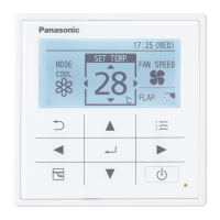
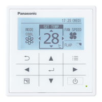
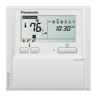
4-1. Part Names
(3) Indication lamp
Indicates operation status.
(1) Light receiving section
Receives signals.
(2) Emergency operation button
Starts/Stops emergency operation.
4-2. Supplied accessories
4-3. Settings
↑ON
Before installing the operation panel,
see the sections on “Wiring for the
Receiver” and “Setting Address
Switches”. Then check the settings of
the operation panel switches.
Main/Sub selector
switch for remote
controllers (4)
OFF: Main ON: Sub
Set its
address
(1) to (3)
All set at OFF
when shipped
from the factory.
Supplied accessories
Wireless
Remote
Controller
(1)
Remote
Control Holder
(1)
LR03 Size
Battery
(2)
Operating
Instructions
(1)
Quick
Reference
(1)
Wood
Screw
M4 × 16
(2)
Pan Head Self-
Tapping Screw
4 × 10
(4)
Clamper
(3)
270059_all.indb 10 2015-1-20 9:53:46
SM830241-00_2WAY SYS.indb 44 2015/03/26 14:55:20
 Loading...