Optional Controller
Manual of Controller
2 - 43
2. Wireless Remote Controller
( CZ-RWSU2N, CZ-RWSD2, CZ-RWST3N, CZ-RWSL2N )
8
CZ-RWSD2
3-1. Part Names
(2) Emergency operation button
Starts/Stops emergency operation.
(1) Light receiving section
Receives signals.
(3) Indication lamp
Indicates operation status.
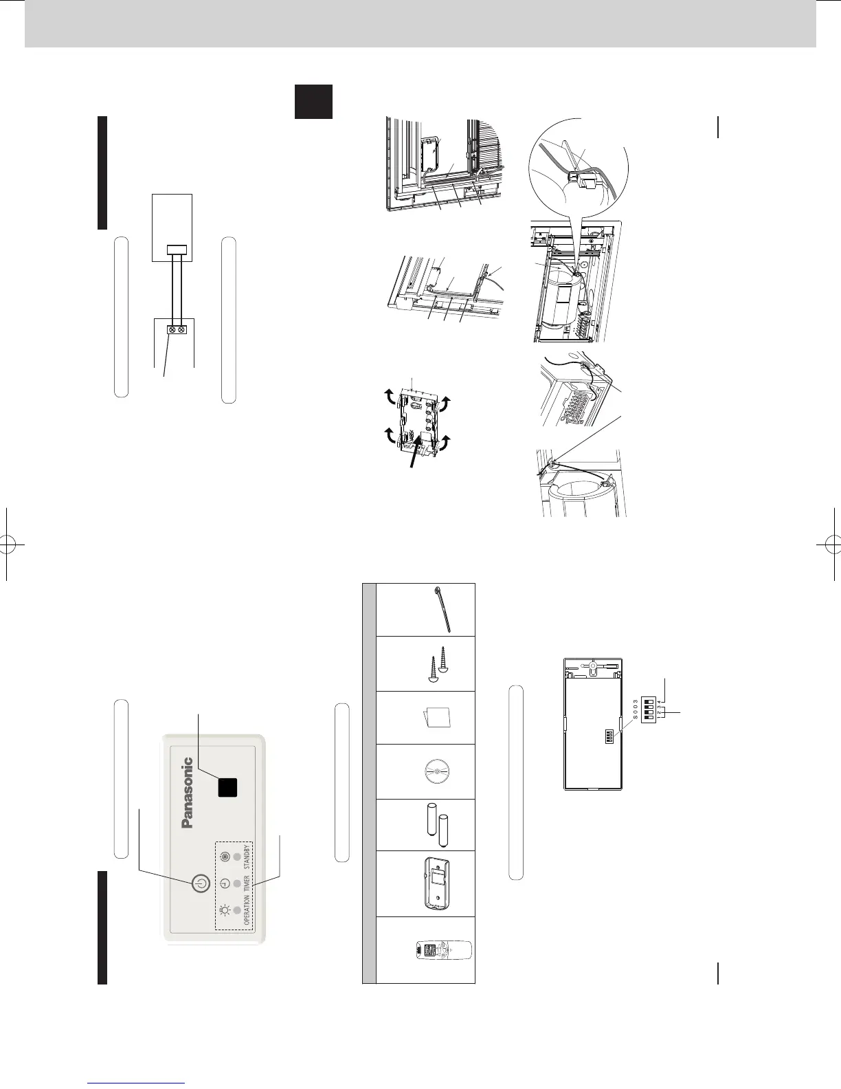
3-2. Supplied accessories
3-3. Settings
Before installing the receiver, see the
sections on “Wiring for the Receiver” and
“Setting Address Switches”. Then check
the setting of the [S003] DIP switch on the
receiver’s PCB.
* Remove the cover from the receiver when
performing the PCB settings.
↑ON
Main/Sub selector
switch for remote
controllers (4)
OFF: Main ON: Sub
Set its address
(1) to (3)
All set at OFF
when shipped
from the factory.
Supplied accessories
Wireless Remote
Controller
(1)
Remote Control
Holder
(1)
LR03 Size
Battery
(2)
Operating
Instructions
(1)
Quick
Reference
(1)
Wood Screw
M4 × 16
(2)
Clamper
(1)
270059_all.indb 8 2015-1-20 9:53:41
9
CZ-RWSD2
ENGLISH
3-5. Installing the Receiver
1 While spreading the tabs of the cover, pull it out from the panel to the front. (Fig. A)
2 When installing on the 1-WAY cassette (high-ceiling), pass the lead wire through the panel and
install the receiver in the hole in the panel. (The projecting parts of the receiver are xed in the
hole in the panel.)
3 Route the lead wire from the receiver along the rib on the back of the panel. Pass it through the
cutout. (Fig. B)
4 Install the panel on the indoor unit.
5 Fasten the lead wire sticking out from the panel with the clamper in the indoor unit. (Fig. C)
6 Draw the lead wire into the electrical box through the hole on the bottom and connect it to the
remote controller terminal board.
When installing to the 1-WAY cassette (high-ceiling), fasten the wire at the latch of the fan
casing with the supplied clamper. (Fig. D)
Fasten the lead wire securely so that it does not get wrapped up in the fan.
For more information about wiring and test operation, see the sections on “Wiring for the Receiver” and
“Test Operation”.
Fig. A Fig. B
Fig. C
Fig. D
Pull out
from the
panel.
Spread
Spread
Insert
the lead
wire.
1-WAY cassette
(high ceiling)
1-WAY cassette
( Back
of the
panel)
Insert
the lead
wire.
Rib
Receiver
1-WAY cassette
(high ceiling)
1-WAY cassette
Cutout
Fan casing
Fasten the wire
at the latch of
the fan casing
with supplied
clamper.
Cover
Clamper
Rib
Receiver
Wiring Diagram
How to Connect the Wires
Connect the wires from the receiver to the terminals for RC
wiring
on the indoor unit. (No polarity)
CN001
1
2
Receiver PCB
Indoor unit
Terminals for RC
wiring
2P white
3-4. Wiring for the Receiver
270059_all.indb 9 2015-1-20 9:53:43
SM830241-00_2WAY SYS.indb 43 2015/03/26 14:55:19
 Loading...