Optional Controller
Manual of Controller
Optional Controller
Manual of Controller
2 - 46
2. Wireless Remote Controller
( CZ-RWSU2N, CZ-RWSD2, CZ-RWST3N, CZ-RWSL2N )
15
Common to All Models
ENGLISH
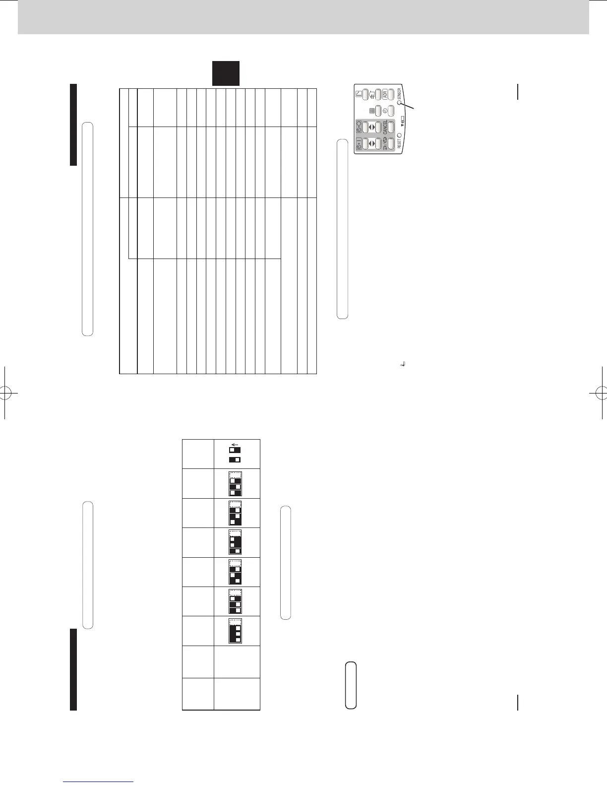
5-5. Room Temperature Sensor Settings
The indoor unit and the wireless remote controller are equipped with
room temperature sensors. The sensing of room temperature works
via one of them.
When the unit is shipped, it is set to the indoor unit. To switch it to the
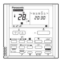
remote controller, press the sensor button (the gure on the right)
inside the remote controller’s cover and then check that Main Sensor
on the LCD screen goes o.
<Note> Be sure to install the remote controller so as to face the
receiver.
If the unit does not receive any room temperature data from
the remote controller for ten minutes even with its sensing
function activated, the indoor unit sensor will automatically
start sensing the room temperature.
Sensor button
5-4. Self-diagnostics table and detected contents
The “Alarm Display” shown in the table below expresses the alarm contents displayed when the
wired remote controller is connected. For how to handle the alarms, see installation instructions
of indoor units or technical guide.
Detected contents Indication lamp on the receiver
Alarm Display
OPERATION TIMER STANDBY
Blinking
Communication error in the remote
controller circuit
E01–E03, E08–E14,
E17, E18
◎
Communication error either in the in/
outdoor operation line or the sub-bus of
the outdoor unit
E04–E07, E15, E16,
E19–E31
◎
Operation of indoor protection device
P01, P09–P14
◎◎
Alternately
Operation of outdoor protection device P02–P08, P15–P31
◎
◎
Alternately
Error in the indoor thermistor F01–F03, F10–F11
◎◎
Alternately
Error in the outdoor thermistor F04–F09, F12–F28
◎◎
Alternately
Error in the indoor EEPROM F29
◎◎
Simultaneously
Error in the outdoor EEPROM F30, F31
◎◎
Simultaneously
Error related to the compressor H01–H31
◎
Error in indoor settings L01–L03, L05–L09
◎
◎
Simultaneously
Error in outdoor settings L04, L10–L31
◎
◎
Simultaneously
Error in the gas heat pump air
conditioner
A01–A31
◎◎
Simultaneously
Inconsistency in Cooling/Heating (Including an auto-temp
setting for a model without auto-temp settings)
◎◎
Alternately
Oil alarm (Same as operation of outdoor protection device)
◎
◎
Alternately
Test operation
◎ ◎◎
Simultaneously
: OFF : ON (Illuminated) ◎: Blinking (0.5 seconds interval)
270059_all.indb 15 2015-1-20 9:53:50
14
Common to All Models
Preparation:
Turn on the circuit breaker of units and then turn the power on. After the power is turned
on, remote controller operation is ignored for approx. 1 minute because setting is being
made. This is not malfunction. (Contents received while setting are disabled.)
1. To start test operation, press and hold the emergency operation button for 10 seconds.
2. The indication lamps (OPERATION, TIMER, STANDBY) blink during test operation.
3. To nish test operation, press and hold the emergency operation button for 10 seconds.
Attention
Do not use this mode for purposes other than
the test operation.
(To prevent overload of the units)
Read the installation instructions supplied with the units.
Any of the Heat, Cool and Fan operations can
only be performed.
Temperature cannot be changed.
The test operation mode is automatically
turned o in 60 minutes.
(To prevent continuous test operation)
Outdoor units do not operate for approx. 3
minutes after the power is turned on or
operation is stopped.
5-3. Test Operation
When more than 1 receiver is installed in the same room, setting addresses prevents
interference.
For how to change addresses of wireless remote controllers, see the operating instructions of
wireless remote controllers.
(CZ-RWSU2N, CZ-RWST3N, CZ-RWSD2)
To change the receiver’s address, remove the cover from the receiver’s PCB and set No.1 to
No.3 of the [003] DIP switch on PCB.
(CZ-RWSL2N)
To change the receiver’s address, set No.1 to No.3 of the [003] DIP switch on PCB on the
control panel.
Remote
Controller
Address
Display
Address Address Address Address Address Address Address
ON/OFF
States
ALL123456
Position
of the
receiver’s
address
switch
Receipt is
possible
at all
of the
address
positions
1234
1234
1234
1234
1234
1234
OFF ON
5-2. Setting Address Switches
270059_all.indb 14 2015-1-20 9:53:49
SM830241-00_2WAY SYS.indb 46 2015/03/26 14:55:22
 Loading...