mapter 2.
sysrem
uverview
secTIon
duo-msrallarion
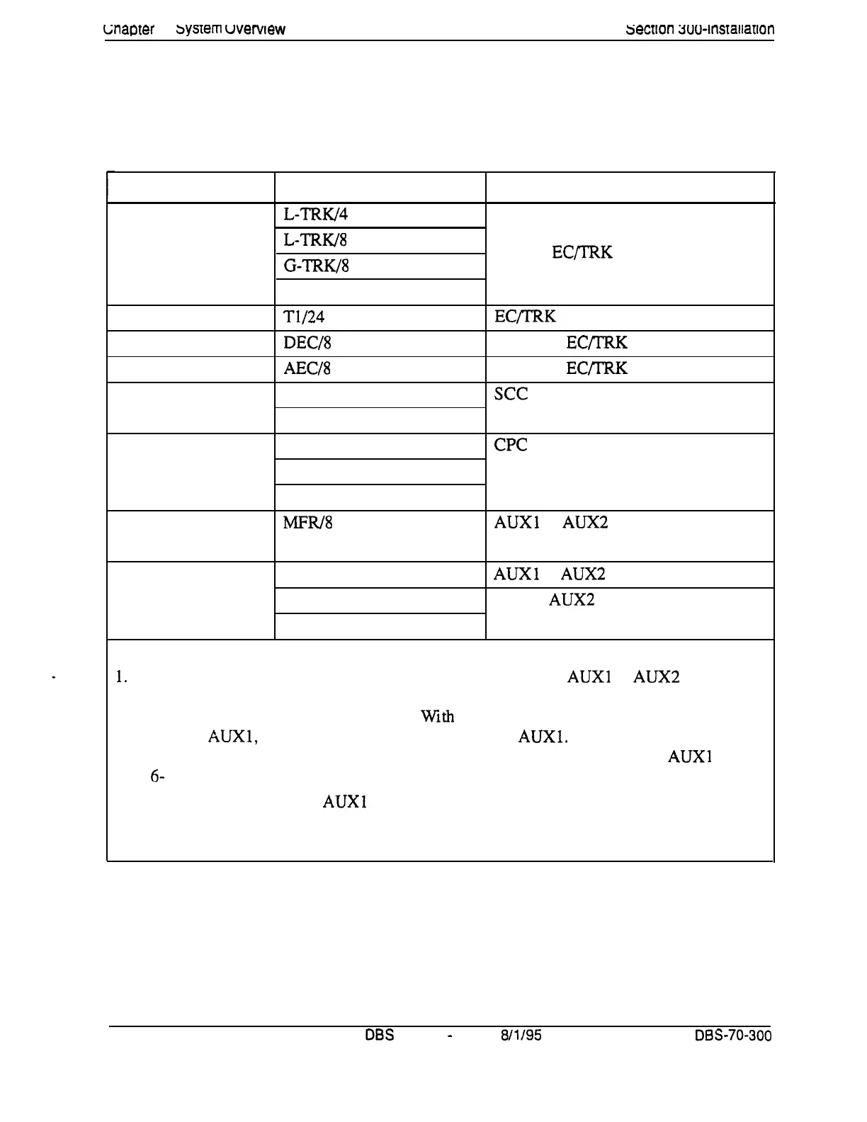
Printed circuit cards are installed in dedicated slots in the DBS cabinet.
Table 2-3 shows the cards that can be installed in each slot. Figure 2-3 on
page 2-9 illustrates slot labels.
Table 2-3. Printed circuit package slot usage
Card Type
Analog
Trunks
Digital Trunks
Digital Lines
Analog Lines
Service
Circuits
Processor Cards
DTMF Circuits
Interface Cards
Notes:
Card
L-TRW4
L-TRK/8
G-TRK/8
DID/8
T1/24
DEC/8
AEC/8
SCC-A
SCC-B
CPC-A
CPC-B
CPC-AI1
MFRl8
API (1 or 2 Circuits)
CBL-M
CBL-S
Acceptable Slots
TRK or EQTRK
EC/TRK
EC l-8 or
EC/IRK
EC 2-8 or
EC/IRK
see
CPC
AUXl or
AUX2
CPC (See Note 1.)
AUXl or
AUX2
(See Note 2.)
CPC or AUX2 (See Note 3.)
1.
With one-cabinet systems, the MFR card can be installed in the
AUXl
or AUX2 slot,
depending on whether an API card is used. With two-cabinet systems, placement of the MFR
cards differs according to the cable kit used.
With
Cable Kit Version 1.1, one MFR is installed
in the Master
AUXl,
and one MFR is installed in the Slave
AUXl.
With Cable Kit Version 1.2,
both MFR cards are installed in the slave cabinet--one in the CPC slot and one in
AUXl . (See
page
6-
10 for instructions on installing MFR cards in double-cabinet systems.)
2. The API card is installed in
AUXl
only when a CBL card is used.
3. Part VB-43 110 includes both the CBL-M and CBL-S cards, as well as the required connect-
ing cables. CBL-M is installed in the master cabinet, CBL-S in the slave cabinet.
2-8
DBS
Manual
-
Issued
8/l/95
DBS-70-300
Technical Manuals Online! - http://www.tech-man.com