Section
300~Installation
Chapter
4.
Trunks and Lines
Loop-Start Trunks
Guidelines
l
Two versions of the loop-start trunk are available: the four-port version
(IQ-435
10) and the eight-port version (VB-43511).
l
The following procedure covers loop-start trunk installation using the main
trunk connector. For instructions on using the expansion trunk connector,
see “Trunk and Line Expansion” on page 4-43
l
For pinouts and color codes for the main trunk connector, see Table 4-2 on
lnstalla tion
page
4-5.
Installation without Caller ID
1.
If installing VB-435
11A
Loop Start Card:
a. Remove the cover from the L-TRK card (VB-435
11A).
b. Set the all option switches to ON as shown in Figure 4-2.
c. Replace the cover on the L-TRK card (VB-43511A).
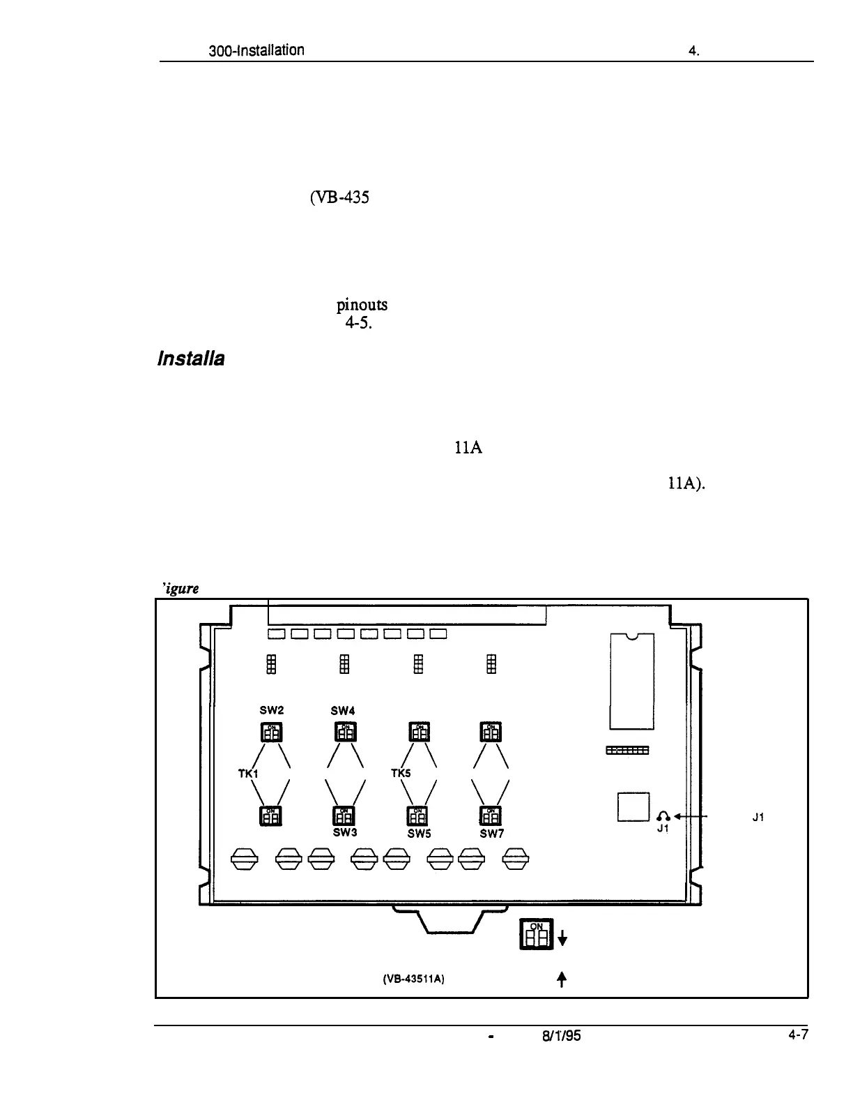
‘igure
4-2. L-TRK Card Strap Jl and Sw itch Locations
SW2
SW4
SW6 SW8
/T
/T
/T
x
TKl
TK2 TK3
TK4
TKS
TK6 TK7
TK8
\/
\/
\/
\/
w
m
EliI
Ial
SW1
SW3
SW5
SW7
-Strap
Jl
must be
cut to
receive
Caller ID
+
When a Caller ID Card Is Installed.
Set All Switches to the OFF Position
L-TRK Card
(VB-43511A)
• il
+
When No Caller ID Card Is Installed,
Set All Switches to the ON Position
DBS-70-300 DBS Manual
-
Issued
8/l/95
4-7
Technical Manuals Online! - http://www.tech-man.com