Chapter 5. Peripheral Equipment
Section
300~Installation
Installation
1.
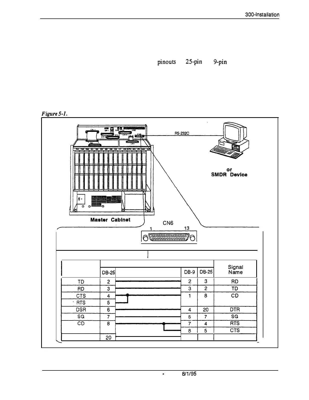
Connect one end of the RS-232C cable to CN6 on the Connector Panel.
Figure 5-l shows cable
pinouts for
25pin
and g-pin RS-232C devices.
These connections have been used successfully with many PCs and
SMDR devices; however, consult the documentation of the PC or SMDR
device before fabricating a cable.
2.
Connect the other end of the RS-232C cable to the local programming
terminal or SMDR device.
Fimre
5-l.
RS-232C connection
Programming Terminal
14
25
Main Cabinet (CN6) RS-232C
1
Prog. Term. or SMDR Printer RS-232C
I
Signal
Pin No. and Connection
Name
lx-25
DE-9
DE-25
“,i,gcJ;
I
DTR
6
1
6
1
DSR
L
5-4
DBS Manual
-
Issued
W/95
DBS-70-300
Technical Manuals Online! - http://www.tech-man.com