FP3 MEWNET-TR
Chapter3-2. Page.39
35
3-2. Wiring
1. Notes on Wiring
x Turn all power OFF before wiring the I/O terminal power supply.
x Do not drop metal particles into the unit when wiring.
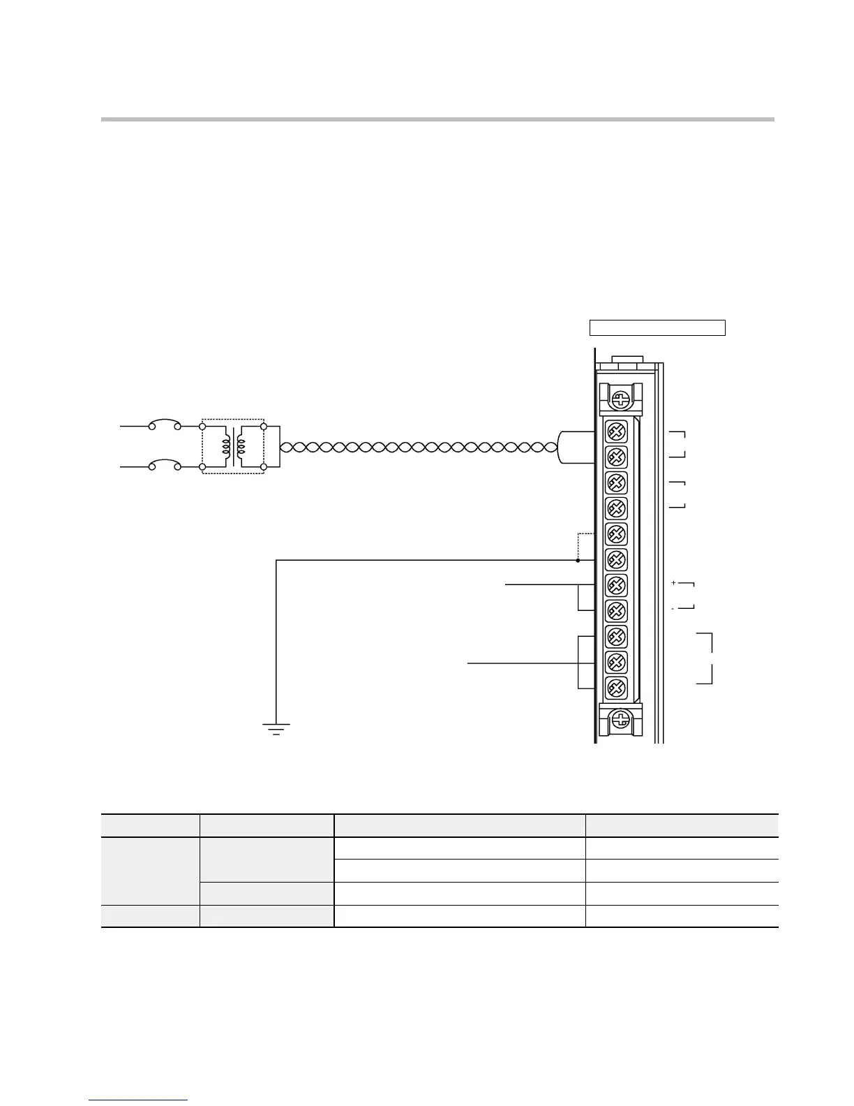
2. Wiring the I/O Terminal Power Supply of the Master Station
J
Diagram of the terminal layout on the power supply unit (using the AFP3631 as example)
Power supply unit
Use different power supplies
for the power supply unit and
the I/O units.
Breaker
Use an insulated
transformer when the
effects of noise are large.
S
Frame ground and
line ground terminals
S
Service power supply terminal
(only on the AFP3631)
Connected to the various I/O units. Can
draw a 24 V power supply. Do not connent
service power supplies to each other, or in
parallel with other power supplies.
S
Voltage switch terminal
(only on the AFP3631)
Shorted: 100 to 120 V AC
Open: 200 to 240 V AC
S
Power supply terminals
Supplies 100 to 120 V AC
or 200 to 240 V AC
(See table below.)
Use a twisted wire that is
thicker than 2 mm
2
for the
electrical wire.
Use a wire that is thicker than 2 mm
2
for the ground wire
S
ALARM output terminal
An alarm output can be output when the
ALARM condition occurs.
100-120/200-240V AC
SHORT: 100-120V AC
OPEN : 200-240V AC
LINE GROUND
FRAME GROUND
0.8A 24V DC
OUTPUT
COM
NO
NC
ALARM
Power supply unit
Type Part No. Rated operating voltage Operating voltage range
AC type AFP3631
100 V to 120 V AC 85 V to 132 V AC
200 V to 240 V AC 170 V to 264 V AC
AFP3636
100 V to 240 V AC 85 V to 264 V AC
DC type AFP3634
24 V DC 16.8 V to 28.8 V DC
3-2. Wiring