FP3 MEWNET-TR
Chapter6-3. Page.88
84
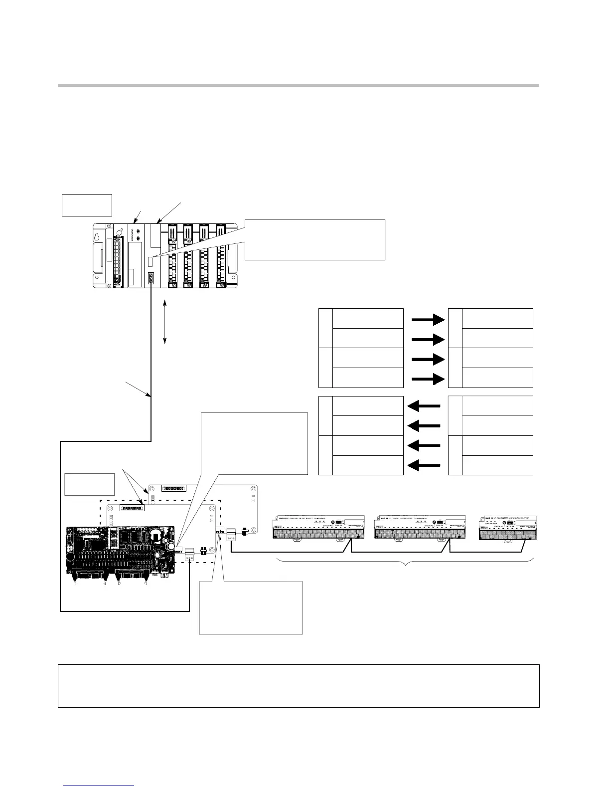
6-3. I/O Link Application Examples
1. FP-M MEWNET-TR System and FP3/FP10S Master Station
x By connecting the RS485 interfaces of the FP-M transmitter master board of an FP-M MEWNET-TR system and the
FP3transmittermasterunitwithatransmissioncable,I/Odatacanbeexchangedbetweentheslave stationsof theFP-M
MEWNET-TR system and the FP3/FP10S master station.
The I/O points allocated to master stations A and B correspond one to one.
J
I/O link function of FP-M MEWNET-TR system and FP3/FP10S master
16-input type
(Station No. 0)
X30 to X3F
Y30 to Y3F
X40 to X47
I/O link function
(I/O data exchange)
FP-M control board
FP-M transmitter
master boards
16-output type
(Station No. 0)
8-input type
(Station No. 4)
FP3 transmitter master unit (mounted in slot number 0 of the master backplane)
Master
station A
FP3/FP10S
CPU
Master
station B
Operation mode selector setting
(setting at 32 inputs/32 outputs)
Inputs: X0 to XF, X10 to X1F
Outputs: Y20toY2F, Y30 toY3F
W
Y
11
Y110 to Y117
Y118 to Y11F
W
Y
12
Y120 to Y127
Y128 to Y12F
X110 to X117
X118 to X11F
W
X
12
X120 to X127
X128 to X12F
W
X
11
X0 to X7
X8 to XF
W
X
1
X10 to X17
X18 to X1F
W
X
0
W
Y
2
Y20 to Y27
Y28 to Y2F
W
Y
3
Y30 to Y37
Y38 to Y3F
FP3/FP10S Master A
(pattern No. 11)
FP-M Master B
(pattern No. 1)
<FP3/FP10S Master A>
Operation mode selector
setting (pattern No.1)
Inputs: X110 to X11F,
X120 to X12F
Outputs: Y110 to Y11F,
Y120 to Y12F
<FP-M Master B>
Operation mode selector
setting (pattern No. 4)
Inputs: X30 to X3F,
X40 to X47
Outputs: Y30 to Y3F
<FP-M MEWNET-TR>
Slave stations (FP I/O transmitter units)
<I/O link function>
Transmission cable
(Twisted pair cable or
2-conductor cable)
Notes:
x
For the I/O allocation pattern numbers of FP-M master B, see the “FP-M/FP1 MEWNET-TR Technical
Manual.”
x
For the pattern numbers of FP3/FP10S master A, see page 64, “3. I/O Allocation Table.”
6-3. I/O Link Application Examples